
Controlling a magnetic resonance imaging system to generate magnetic resonance image data of an examination subject

a magnetic resonance imaging and image data technology, applied in the direction of magnetic measurement, measurement using nmr, instruments, etc., can solve the problem that the minimum time between sampling events that results from adherence to a strict nyquist-shannon sampling rate can, in certain situations, be severely limited, and achieve the effect of quick implementation

Active Publication Date: 2019-01-08
SIEMENS HEALTHCARE GMBH
View PDF7 Cites 0 Cited by
  • Summary
  • Abstract
  • Description
  • Claims
  • Application Information

AI Technical Summary

Benefits of technology

The invention provides a way to quickly and accurately acquire magnetic resonance data to reconstruct high-quality images. By using sparse sampling of readout pairs instead of individual readout points, eddy current effects can be minimized, allowing for faster acquisition without quality loss. The system uses a control sequence determination software program that can be easily installed in existing imaging systems. Additionally, the use of a linear sampling function and a partial Fourier method can further accelerate the acquisition process with a desired spatial resolution. The system also utilizes the pseudorandom principle to generate raw magnetic resonance data with a limited number of presentation coefficients, allowing for sparse depiction of k-space.

Problems solved by technology

The minimum time between sampling events that results from adherence to a strict Nyquist-Shannon sampling rate can, in certain situations, be severely limiting, for example if the generation of image data of a moving examination subject is sought.

Method used


Image

  • Controlling a magnetic resonance imaging system to generate magnetic resonance image data of an examination subject
  • Controlling a magnetic resonance imaging system to generate magnetic resonance image data of an examination subject
  • Controlling a magnetic resonance imaging system to generate magnetic resonance image data of an examination subject

Examples


Embodiment Construction

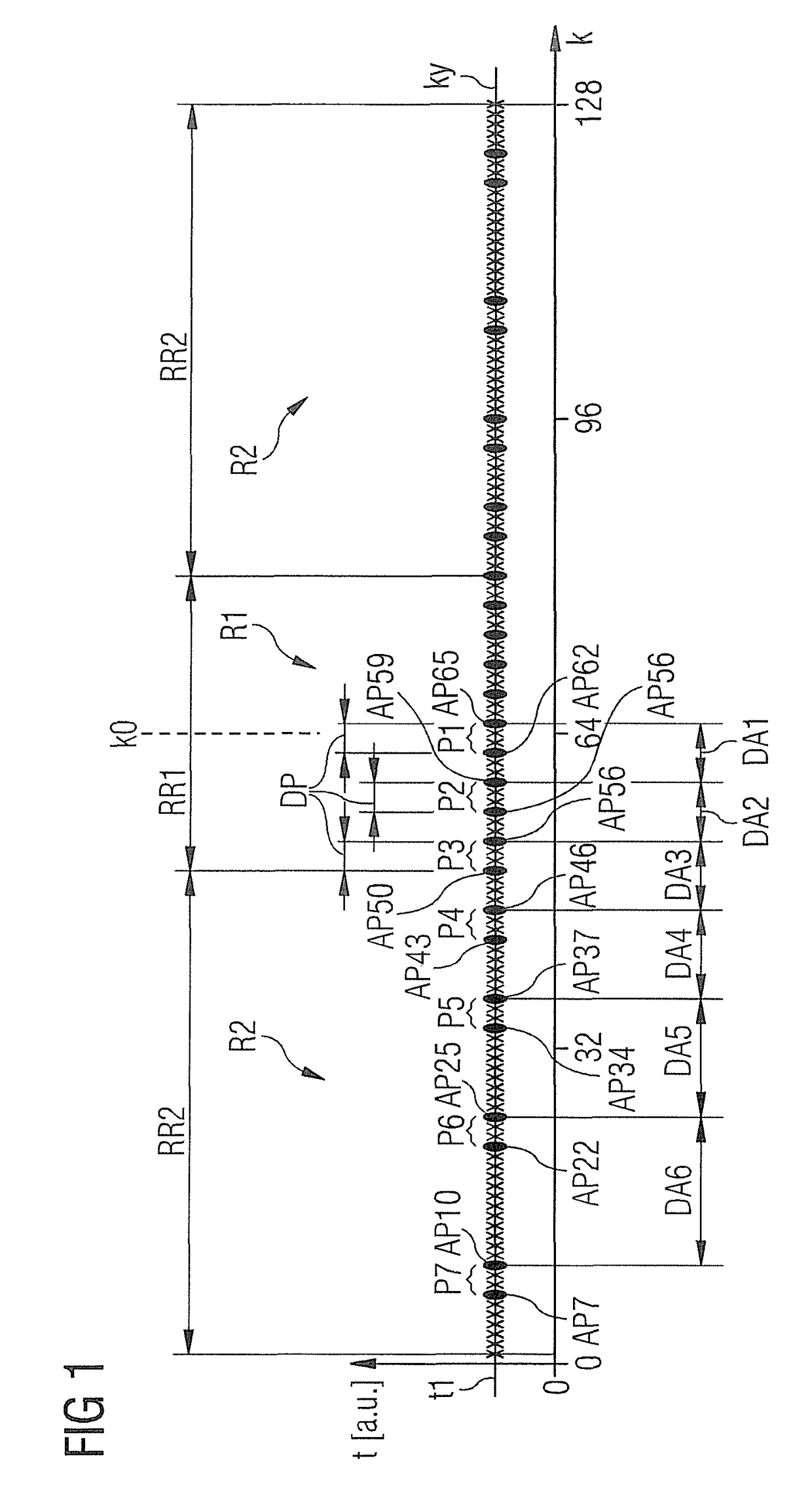
[0046]FIG. 1 shows a readout axis ky that proceeds in k-space orthogonally to a trajectory for sampling of k-space to acquire raw magnetic resonance data of an examination subject. In this, as in all further exemplary embodiments, magnetic resonance signals should be acquired according to a bSSFP method.

[0047]As is apparent in contribution with FIG. 5, the examination subject O is situated in the measurement space 8 of a magnetic resonance imaging system 1 to acquire raw magnetic resonance data RD. The spatial coding of the raw magnetic resonance data RD ensues as is typical in k-space, which is associated with spatial regions of the examination subject O (and therefore of the measurement space 8) via a Fourier transformation.

[0048]FIG. 1 shows the chronological order of the sampling of k-space along a readout axis ky. The readout axis ky proceeds parallel to the ky-direction of k-space, i.e. parallel to the frequency coding direction. As previously noted, the raw magnetic resonance...


PUM


Abstract

In a method to control a magnetic resonance imaging system to generate magnetic resonance image data of an examination subject, raw magnetic resonance data are acquired that include measurement values at multiple readout points in k-space. The readout points are arranged along a readout axis in k-space as readout pairs with a predetermined pair spacing relative to one another. Readout pairs that are adjacent in k-space along the readout axis have a sampling interval that is different than the pair spacing, which sampling interval varies along the readout axis. A control sequence determination system is designed to determine a control sequence for a magnetic resonance imaging system that is designed to control the magnetic resonance imaging system according to this method, and a magnetic resonance imaging system that has a control device designed to control the magnetic resonance imaging system according to such a method.

Description

BACKGROUND OF THE INVENTION[0001]Field of the Invention[0002]The invention concerns a method for controlling a magnetic resonance imaging system to generate image data of an examination subject, a control sequence determination system to determine such a control sequence, and a magnetic resonance imaging system designed for operation according to such a method.[0003]Description of the Prior Art[0004]Imaging systems that make use of a magnetic resonance measurement (signals originating from nuclear spins) are known as magnetic resonance tomography systems and have been successfully established and proven for a multitude of applications. In this type of image acquisition, a static basic magnetic field BO, which serves for initial alignment and homogenization of magnetic dipoles that are to be examined, is superimposed with a rapidly switched magnetic field (known as the gradient field) for spatial resolution of the imaging signal. To determine material properties of an examination sub...

Claims


Application Information

Patent Timeline
Patent Type & Authority Patents(United States)
IPC IPC(8): G01R33/48G01R33/385G01R33/561G01R33/54G01R33/563
CPCG01R33/482G01R33/3852G01R33/5611G01R33/543G01R33/56325G01R33/5614
Inventor ZENGE, MICHAEL
Owner SIEMENS HEALTHCARE GMBH
Learn More