Supercharge Your Innovation With Domain-Expert AI Agents!

RIFD tag with a tunable antenna

a tunable antenna and rfid tag technology, applied in the field of rfid tags and labels, can solve the problems of reducing the sensitivity performance of the chip, creating energy losses, and prior art slotted uhf rfid tags having temperature limitations

Active Publication Date: 2019-01-08
ASSA ABLOY AB
View PDF29 Cites 6 Cited by
  • Summary
  • Abstract
  • Description
  • Claims
  • Application Information

AI Technical Summary

Benefits of technology

Enables easy frequency adjustment and prevents gas accumulation, maintaining performance in metallic environments and high temperatures, reducing the need for additional impedance matching circuits and improving tag reliability.

Problems solved by technology

For UHF, this is bad news since at UHF frequencies the reflected waves from the metal is added to incident waves in a destructive way, and therefore the UHF antenna inside the tag collects a very weak signal / very small energy to feed the UHF chip.
Furthermore, an adaptive circuit dedicated to impedance matching will create energy losses and since UHF RFID tags are passive tags they only use the power from a radio wave source.
Therefore any energy loss will strongly reduce the sensitivity performance of the chip.
In addition, it is known that such prior art slotted UHF RFID tags have temperature limitations and they usually only withstand a maximum temperature of 65° C. according to storage temperature tests that have been carried out.
Because the Q-factor is high, any slight de-tuning has the consequence of rendering the tag practically unusable.
Thus, it is necessary to maintain as much as possible the precise resonance frequency of the tag avoiding any de-tuning, even in extreme conditions such as high temperature, otherwise the tags will not perform as expected in the considered environment.

Method used


Image

  • RIFD tag with a tunable antenna
  • RIFD tag with a tunable antenna
  • RIFD tag with a tunable antenna

Examples


Embodiment Construction

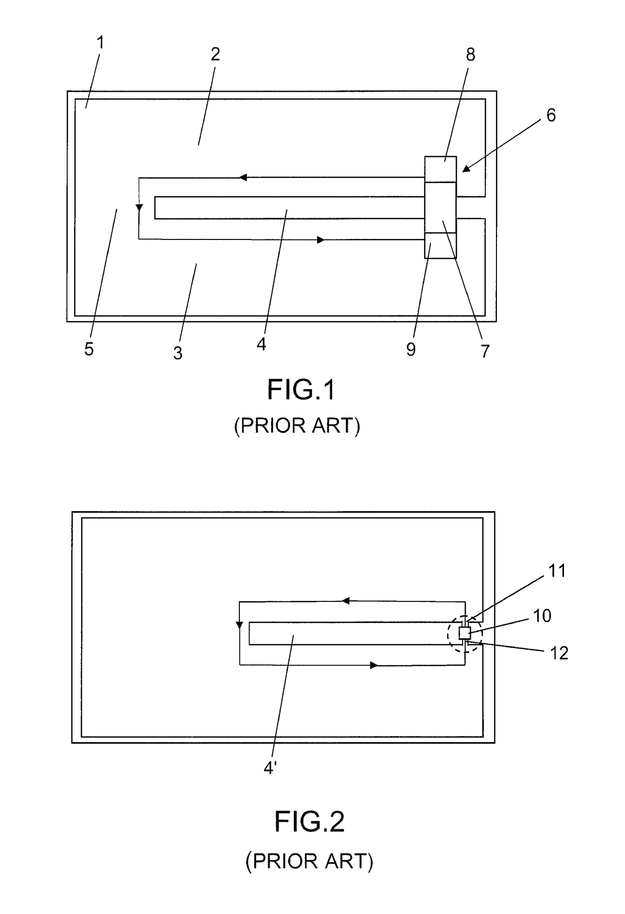
[0061]In FIG. 1, an illustration of a RFID tag of the prior art is given as an example. Typically, this representation corresponds to an embodiment of US'677 discussed above.

[0062]This tag comprises, for example, a substrate layer 1 on which an antenna is placed. The antenna comprises a first part 2, a second part 3 and both parts 2, 3 are separated by a slot 4. The closed end 5 of the slot 4 make a bridge between the two parts of the antenna 2, 3. An RFID device 6 is mounted on the two antenna parts 2, 3 at the open end of the slot 4. The RFID device 6 comprises a chip module comprising a chip 7 mounted on two conductive pads 8 and 9 which are respectively coupled to parts 2 and 3.

[0063]The arrows in FIG. 1 illustrate the circuit path from one side of the chip 8 to the other along the first and second parts 2, 3 of the antenna over the closed end 5 of the slot 4.

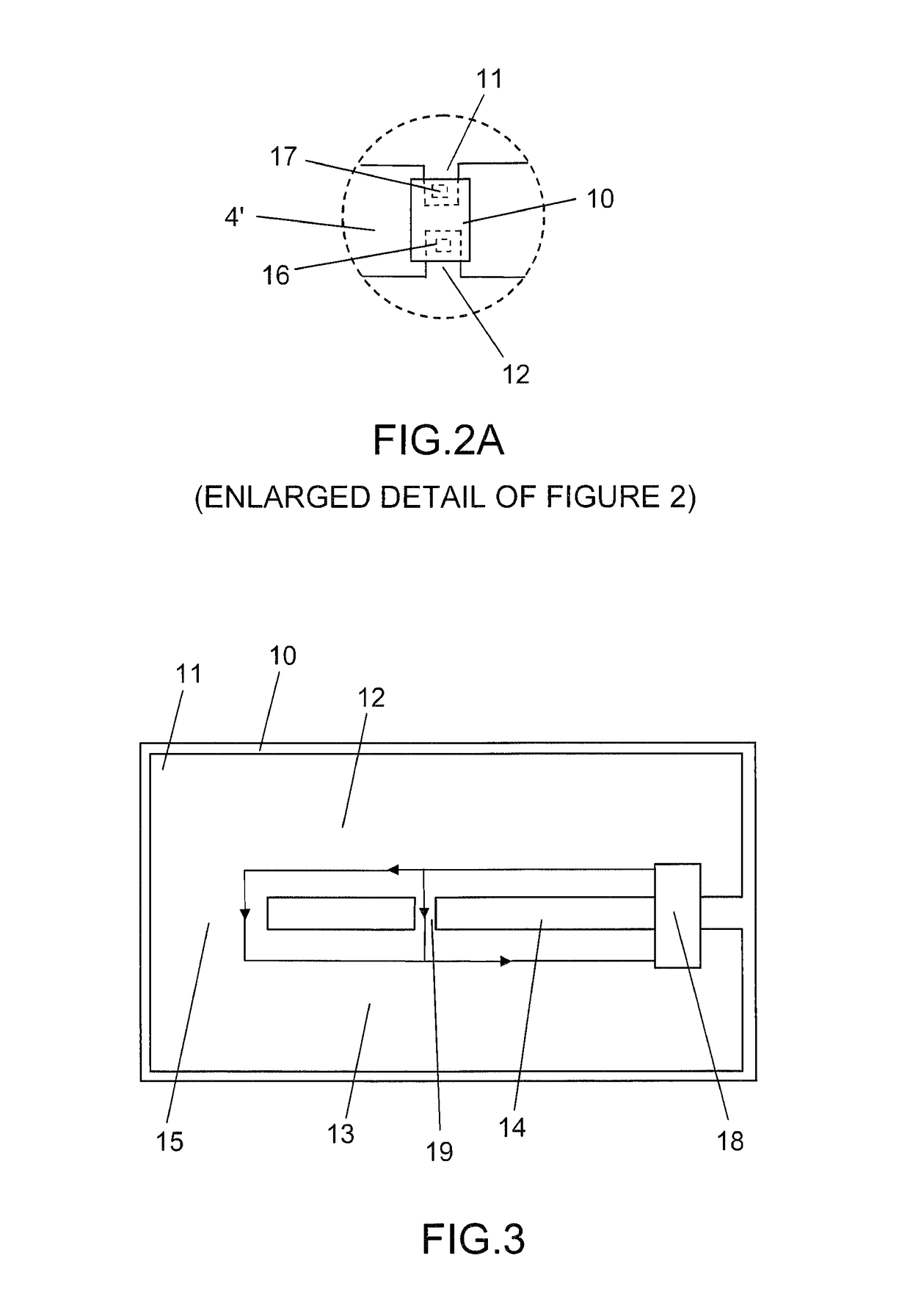
[0064]Alternatively, as illustrated in FIG. 2, the RFID device 10 could consists simply of a RFID chip with connection pa...


PUM


Abstract

The RFID tag comprises an antenna (11) connected to a wireless communication device (18). The antenna comprises a conductive planar surface and a slot (14) extending at least in a part of said conductive planar surface, the slot (14) forming a non-conductive area of the antenna and defining a first part (12) and a second part (13) of the antenna. The wireless communication device comprises two contact pads (16, 17) being electrically connected respectively each to one of the first and second part of the antenna. The slot comprises a closed end formed by a further conductive part connecting said first and second parts the antenna and further comprises at least one conductive bridge (19-19′″, 20, 21-21″) connecting said first and second parts of the antenna, the conductive bridge allowing to tune the resonance frequency of the tag by varying the length of the electrical path between the pads from the wireless communication device in the antenna.

Description

CROSS REFERENCE TO RELATED APPLICATIONS[0001]This application is a national stage application under 35 U.S.C. 371 and claims the benefit of PCT Application No. PCT / IB2015 / 054347 having an international filing date of 9 Jun. 2015, which designated the United States, the disclosures of which are incorporated herein by reference in its entirety.TECHNICAL FIELD[0002]The present invention concerns the RFID tags and labels, and more particularly the field of tags and labels that comprise an antennaBACKGROUND ART[0003]UHF RFID tags and labels are often designed to meet customer requirements in term of mechanical strength, thermic resistance and read range performance.[0004]Low cost, popular UHF RFID tags for industry and logistics applications comprise, in general a UHF inlay packaged in a housing (generally made of plastic) containing the inlay in order to protect the fragile antenna and chip from outdoor conditions: rain, impact shocks, snow, dust etc . . . .[0005]As example, a UHF inlay...

Claims


Application Information

Patent Timeline
Patent Type & Authority Patents(United States)
IPC IPC(8): G06K19/06G06K19/077H01Q1/22H01Q13/10H01Q9/04
CPCG06K19/07773H01Q1/2225H01Q13/103H01Q13/10H01Q9/0421
Inventor ENNABLI, ELIESROBADEY, JEAN-MIGUELMIRUS, CHRISTIAN
Owner ASSA ABLOY AB
Features
  • R&D
  • Intellectual Property
  • Life Sciences
  • Materials
  • Tech Scout
  • Unparalleled Data Quality
  • Higher Quality Content
  • 60% Fewer Hallucinations
Learn More