Medical knife

a technology for medical devices and blades, applied in the field of medical devices, can solve the problems of high manufacturing cost, affecting the accuracy of the blade, and the ability to adjust the spacing of the two blades, and achieve the effect of convenient assembly, easy manufacturing, and convenient blade spacing chang

Active Publication Date: 2019-01-15
KAI R&D CENT CO LTD
View PDF126 Cites 0 Cited by
  • Summary
  • Abstract
  • Description
  • Claims
  • Application Information

AI Technical Summary

Benefits of technology

[0006]An object of the present invention is to provide a medical knife that can be assembled with different blade spacings, even though the handles are molded in the same shape.
[0012]In the first aspect of the invention, a pair of side walls are provided on the two sides of the handle, at least in the forward portions thereof, the side walls being formed individually on different handle-constituting parts, and a pair of blades are separately mounted on the insides of these side walls. Thus, the handle before being assembled in a medical knife is deformable, such that the two handle-constituting parts forward of the connecting part can be spread apart and closed together, centered on the connecting part, and such that the spacing distance between the two side walls is adjustable. Accordingly, when the blades are mounted on the insides of the side walls, the spacing distance between the two side walls is adjustable in keeping with a blade spacing that has been determined in advance, which makes it possible to support knife assemblies with different blade spacings. Furthermore, the handle-constituting parts of the handle before being assembled in a medical knife that is formed is such that the two handle-constituting parts forward of the connecting part can be spread apart and closed together, centered on the connecting part. Accordingly, the handle before assembly can be formed in a configuration in which there is a relative offset between the two side walls, while the spacing between the two side walls is maintained, and the two side walls can be caused to face each other at the time of assembly. Consequently, if the pair of blades are not mounted at the same time on the handle, but rather are mounted on the side walls at different times, the side wall in which the blade is not mounted will not be an obstacle to mounting, such that it will be possible to mount the blade easily.
[0013]The invention of the second aspect is configured such that at least one of the handle-constituting parts in the pair of handle-constituting parts is formed from a flexible material; the invention of the third aspect is configured such that the connecting part is formed by a thin hinge; and the invention of the fourth aspect is configured such that the pair of handle-constituting parts and the connecting part that connects the pair of handle-constituting parts are integrally formed from the same flexible material. Thus, with this configuration, the handle before being assembled in a medical knife is such that the handle-constituting parts forward of the connecting part can be spread apart and closed together, centered on the connecting part, and the spacing distance between the two side walls is adjustable, and thus assembly is easy.
[0014]The invention of the fifth aspect is such that a spacing maintenance member for maintaining a constant spacing between the two side walls is mounted between the two side walls. Accordingly, the spacing between the side walls can be easily and accurately ensured by the spacing maintenance member. Furthermore, the spacing between the two side walls can be changed by changing the lateral width of the spacing maintenance member.
[0015]The invention of the sixth aspect is configured such that the pair of blades are each separately trapped between the spacing maintenance member and a side wall. Accordingly, if the width, in the spacing direction, of the spacing maintenance member is made to be the same as the intended spacing of the blades, a medical knife having the intended blade spacing the can easily be manufactured. Furthermore, the blade spacing can easily be changed by changing the spacing maintenance member. The invention of the seventh aspect is such that an insertion hole is formed in the blades; a fitting hole is formed in the side walls; fitting protrusions are formed on the two sides of the spacing maintenance member; and the fitting protrusions are inserted into the insertion holes in the blades and fitted into the fitting holes in the side walls so as to mount the spacing maintenance member and the blades between the side walls. Accordingly, blade mounting and medical knife assembly can be performed by inserting the fitting protrusions on the spacing maintenance member into the insertion holes in the blades, and fitting these fitting protrusions into the fitting holes in the side walls, which facilitates assembly and reduces manufacturing time.
[0016]The invention described in claim 8 is such that the handle has a top wall and a bottom wall in a forward portion thereof, on which fingertips can be placed during use, the top wall being formed in a first handle-constituting part and the bottom wall being formed in a second handle-constituting part. Accordingly, the top wall and the bottom wall can be used for finger placement when the knife is used, allowing for stable work. Furthermore, the handle-constituting parts respectively comprise the side walls and the top wall or bottom wall, the cross-sections of those portions each forming an L shape. Consequently, there will be no interference by the top wall or the bottom wall when the spacing between the two side walls is changed in the handle before being assembled.

Problems solved by technology

With the knife described in U.S. Pat. No. 5,026,385, it is not possible to adjust the spacing of the two blades, and therefore knives with different blade spacings must be provided.
Accordingly, separate molds are necessary in order to manufacture the knives with the different blade spacings, and costs are correspondingly increased.
However, if this entire knife is used as a disposable item, the manufacturing costs will be high, which has poor profitability.

Method used


Image

  • Medical knife
  • Medical knife
  • Medical knife

Examples


Embodiment Construction

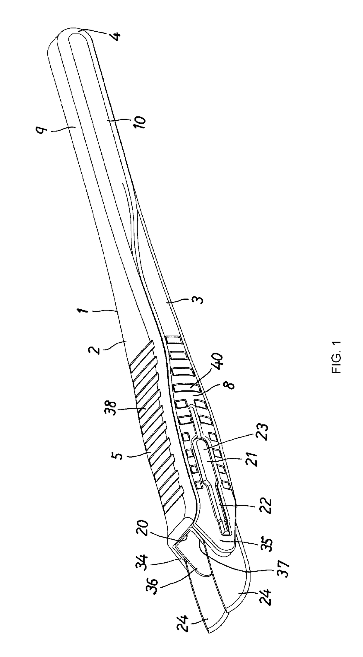
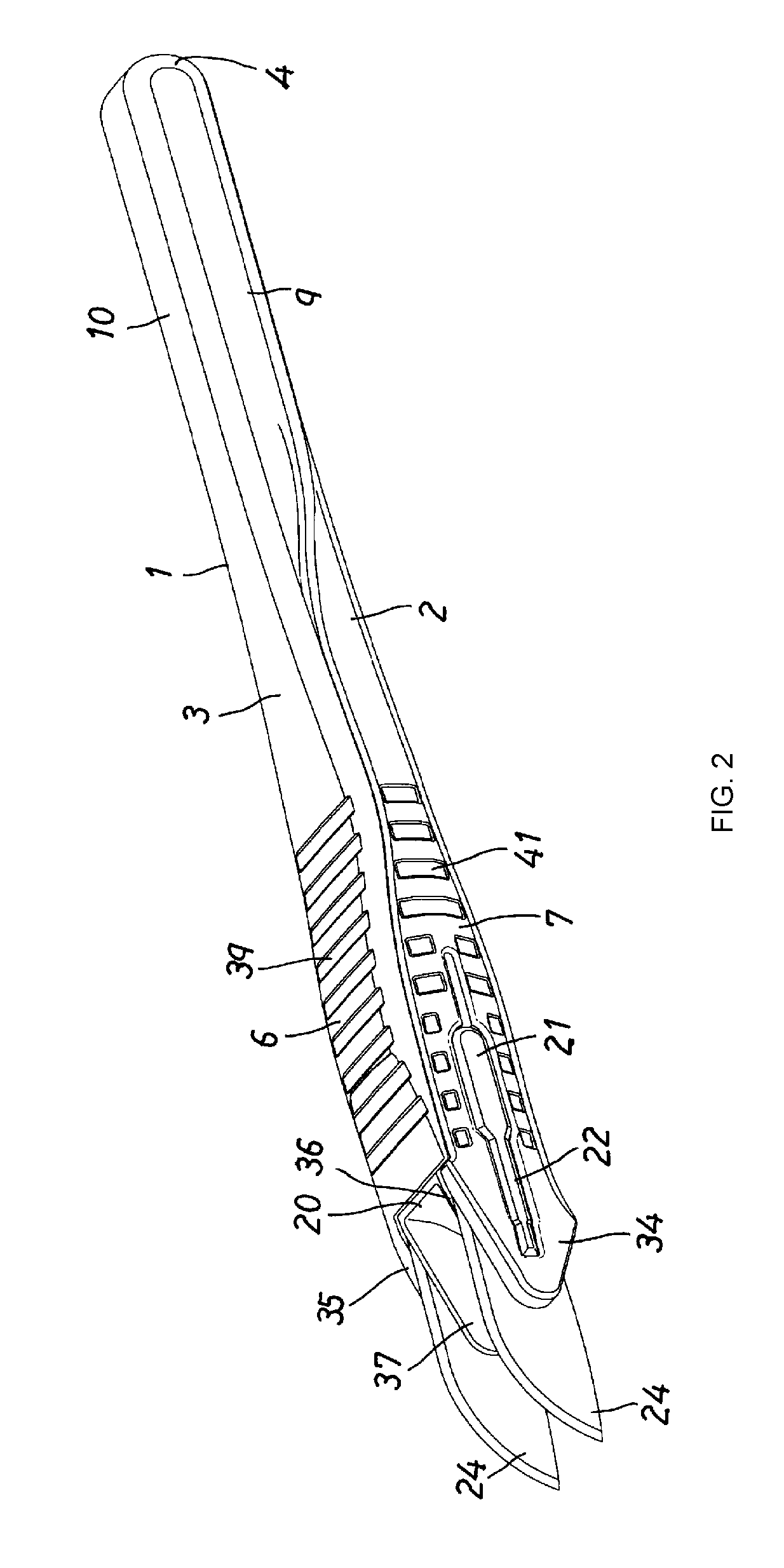
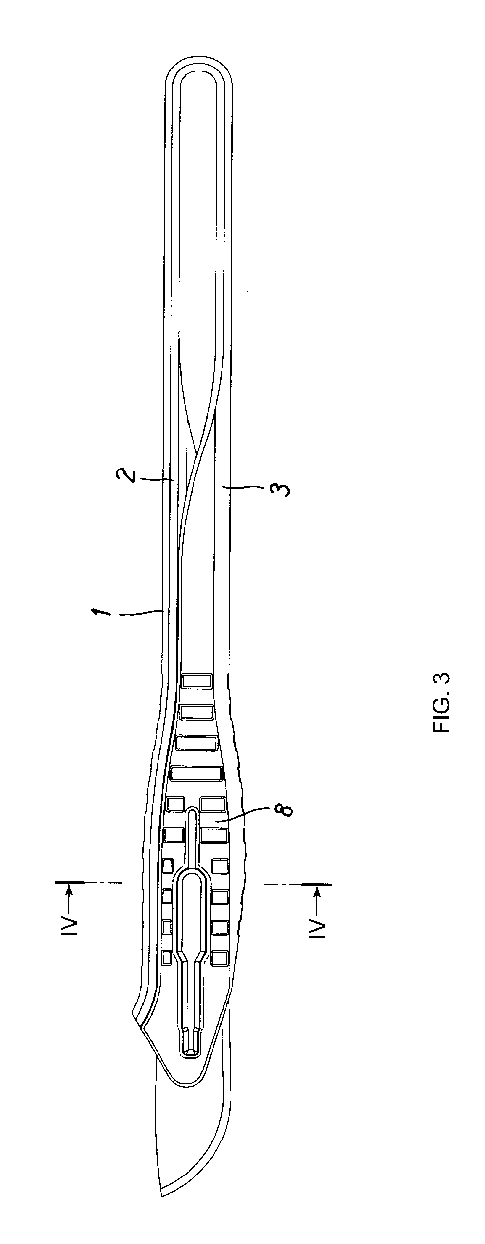
[0026]Next, embodiments of the present invention are described with reference to the drawings. Note that, in the present embodiment, the entire knife is disposable. As shown in FIG. 5 and FIG. 6, a handle 1 before being assembled in a medical knife is formed in the shape of tongs, and the handle-constituting parts 2, 3 of the handle 1 before assembly are formed in an already open configuration. Furthermore, as shown in FIG. 5, in the handle 1 before assembly, the handle-constituting parts 2, 3 face each other and, as shown in FIG. 7, these are formed in a configuration such that these are not offset from each other in the lateral width direction.

[0027]The handle 1 is formed from a flexible material, and for example, is integrally formed by injection molding a flexible thermoplastic resin such as polypropylene or polyethylene. The handle-constituting parts 2, 3 of the handle 1 are integrally joined by way of a U-shaped connecting part 4 at the rear ends thereof. As shown in FIG. 1 an...


PUM


Abstract

A medical knife that can be assembled with different blade spacings, provided with only one handle includes a pair of side walls on respective sides of the handle, at least in the forward portions of the handle the side walls being formed individually on different handle-constituting parts and a pair of blades separately mounted on the insides of these side walls; and the handle before being assembled to constitute a medical knife is configured such that the two handle-constituting parts forward of a connecting part can be spread apart and closed together, centered on the connecting part, and such that the spacing distance between the two side walls is adjustable.

Description

BACKGROUND OF THE INVENTION[0001]The present invention relates to a medical knife, in which a pair of blades are mounted in parallel, spaced apart, at the front of a handle.[0002]Medical knives in which a pair of blades are mounted in parallel, spaced apart, as in the present invention, are primarily used to cut tissue at a predetermined width, these being medical knives which are used, for example, in surgery for anterior cruciate ligament reconstruction in the knee, for severing the patellar tendon, for making incisions into bones when collecting tibia plugs or patella plugs, or for collecting tissue at a predetermined widths or the like, while maintaining the spacing of the blades.[0003]Medical knives include those which, after use, are washed and undergo resterilization and are then reused, and those that are disposable. Recently disposable medical knives are often used, in light of the costs of infection prevention and resterilization. The medical knife of the present invention...

Claims


Application Information

Patent Timeline
Patent Type & Authority Patents(United States)
IPC IPC(8): A61B17/3211B26B5/00A61B17/3213A61B17/00
CPCA61B17/3211A61B17/3213B26B5/008A61B2017/00831A61B2017/00473A61B2017/0023A61B17/00008
Inventor ENDO, MASAHIRO
Owner KAI R&D CENT CO LTD
Why Eureka
Try Eureka