Rotor for a centrifugal separator and centrifugal separator
a centrifugal separator and rotor technology, applied in the direction of centrifuges, rotary centrifuges, machines/engines, etc., can solve the problems of cost-effectiveness
- Summary
- Abstract
- Description
- Claims
- Application Information
AI Technical Summary
Benefits of technology
Problems solved by technology
Method used
Image
Examples
first embodiment
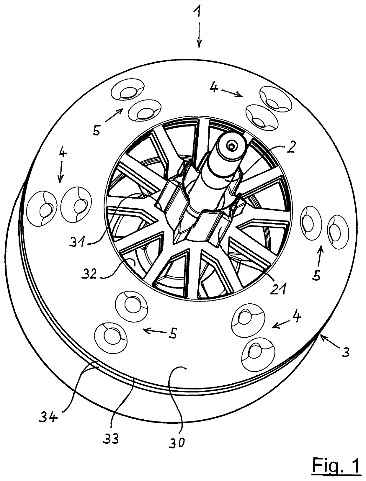
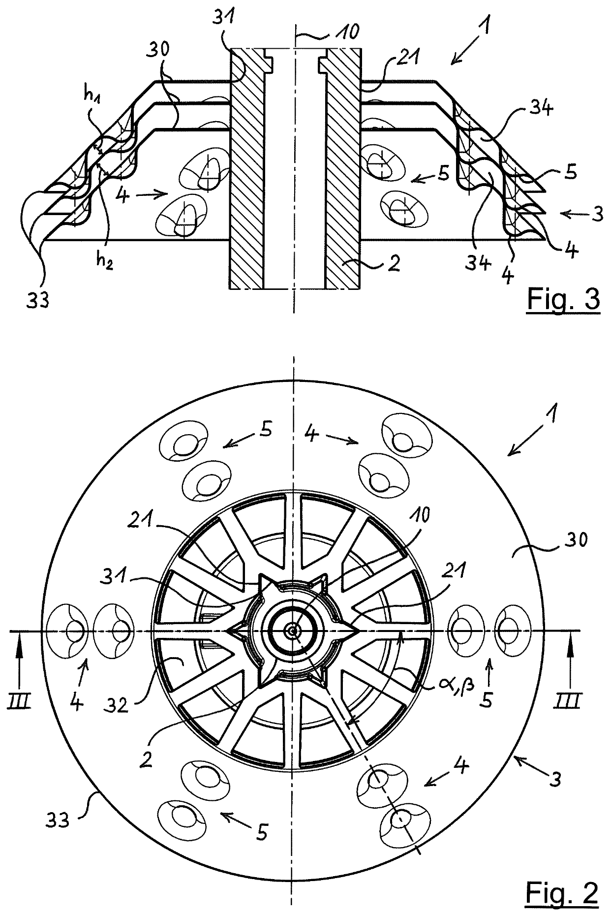
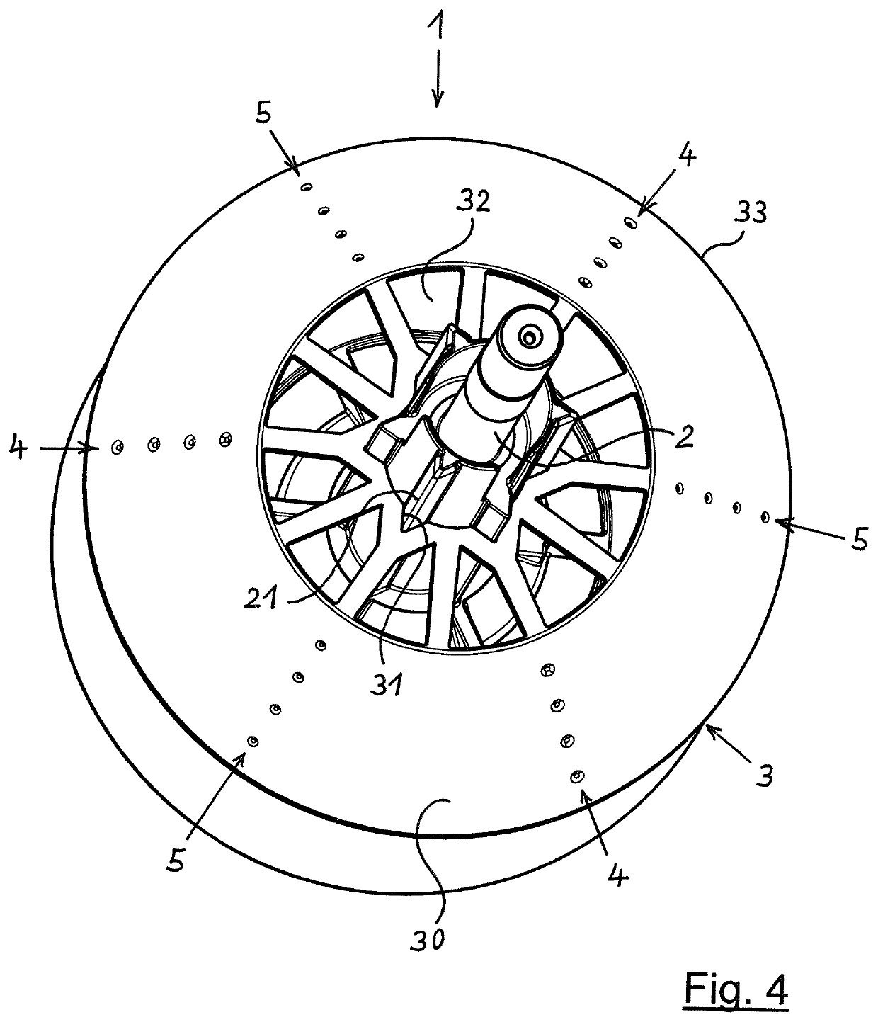
[0056]FIGS. 1 through 3 of the drawing show a rotor 1 of a centrifugal separator (otherwise not shown), in a Rotor 1 has a central shaft 2 on which a disc stack 3 made up of a plurality of identical discs 30 is situated. Discs 30 here each have the known shape of a frustum-shaped jacket, and may be made of sheet metal or plastic. For ease of representation, in FIG. 1 only a few discs 30 are shown; in practice, a disc stack 3 will have up to 100 or more discs 30.
[0057]Shaft 2 has on its outer circumference an engagement contour 21 for rotationally fixed, axially slidable engagement with a corresponding contour 31 on the inner circumference of disc 30 of disc stack 3, engagement contour 21 here having the shape of a six-pointed star. Engagement contour 21 and corresponding contour 31 can be brought into engagement with one another in a plurality of relative rotational positions that are at a grid angular distance α, here 60°, from one another in the circumferential direction.
[0058]Ra...
third embodiment
[0077]FIGS. 8 through 11 show rotor 1 in a Differing from the previously described embodiments of rotor 1 is that here first and second spacing elements 4, 5 are formed by webs that are attached to or integrally formed on discs 30 and that form raised parts. The spacing elements 4, 5 formed by the webs here run in a straight line in the radial direction. Alternatively, spacing elements 4, 5 may also run in a curve.
[0078]The webs forming first spacing elements 4, here three pieces, are situated on the upper side of disc 30, and the webs forming second spacing elements 5, also three pieces, are situated on the lower side of disc 30. Moreover, here the webs forming first spacing elements 4 are offset relative to the webs or nubs forming second spacing elements 5 in the circumferential direction of disc 30. The angular distance β of the three webs, forming first spacing elements 4, to one another is here 120° in each case. The angular distance β of the three webs forming second spacing...
fourth embodiment
[0082]FIGS. 12 through 15 show rotor 1 in a Agreeing with the above-described exemplary embodiment of rotor 1 according to FIGS. 8 through 11, here as well first and second spacing elements 4, 5 are formed by webs that are attached to or integrally formed on discs 30 and that form raised parts.
[0083]The webs that form first spacing elements 4, here three pieces, are situated on the upper side of disc 30, and the webs, also three pieces, forming second spacing elements 5 are situated on the lower side of disc 30. Differing from the exemplary embodiment described above of rotor 1 according to FIGS. 8 through 11, here the upper-side webs forming first spacing elements 4 are situated so as to congruently overlap with the lower-side webs forming second spacing elements 5. The angular distance β of the three webs forming first spacing elements 4 from one another is here 120° in each case. The angular distance β of the three webs forming second spacing elements 5 is likewise 120° in each ...
PUM
 Abstract
Description
Claims
Application Information
 - R&D
- Intellectual Property
- Life Sciences
- Materials
- Tech Scout
- Unparalleled Data Quality
- Higher Quality Content
- 60% Fewer Hallucinations
Browse by: Latest US Patents, China's latest patents, Technical Efficacy Thesaurus, Application Domain, Technology Topic, Popular Technical Reports.
© 2025 PatSnap. All rights reserved.Legal|Privacy policy|Modern Slavery Act Transparency Statement|Sitemap|About US| Contact US: help@patsnap.com


