Method and system for utilizing proximity lighting and plug controls for real time location sensing

a technology of proximity lighting and plug controls, applied in the direction of computer control, program control, instruments, etc., can solve the problems of limited spatial and temporal accuracy for a limited number of devices, and achieve the effect of cost-effectiveness and ease of installation

Active Publication Date: 2019-01-15
BCP CONTROLS
View PDF5 Cites 2 Cited by
  • Summary
  • Abstract
  • Description
  • Claims
  • Application Information

AI Technical Summary

Benefits of technology

[0004]An object of the present invention is to provide a system for monitoring user or equipment location in or around a building or buildings based on the detection of their proximity to various light fixtures or electrical plugs located regularly and ubiquitously throughout or around a facility or group of facilities. Another object of the present invention is to provide continuous tracking of the user or equipment as it moves through a facility in proximity to the lighting and electrical plugs. Another object of the present invention is to provide controls to the system to allow flexibility in temporal and spatial resolution of the solution based on user established requirements. These objects of the invention enable various solutions that may not be achievable by other systems for tracking accuracy, tracking large numbers of items, tracking of a high spatial density of individual items, or for rapidly tracking individual devices.

Problems solved by technology

Typically these systems require the addition of infrastructure installations of various dedicated receivers or instrumentation both in the building and on the user and provides limited spatial and temporal accuracy for a limited number of devices.

Method used


Image

  • Method and system for utilizing proximity lighting and plug controls for real time location sensing
  • Method and system for utilizing proximity lighting and plug controls for real time location sensing
  • Method and system for utilizing proximity lighting and plug controls for real time location sensing

Examples


Embodiment Construction

[0016]In the following description of the present invention there are multiple details established to provide a thorough understanding of the invention and the preferred implementations of the invention. It should be clear that the description is not intended to limit the invention to these specific embodiments and those variations, changes, substitutions, or equivalent components will be apparent to those skilled in the art and should not be considered significant differences from the intended scope of the invention.

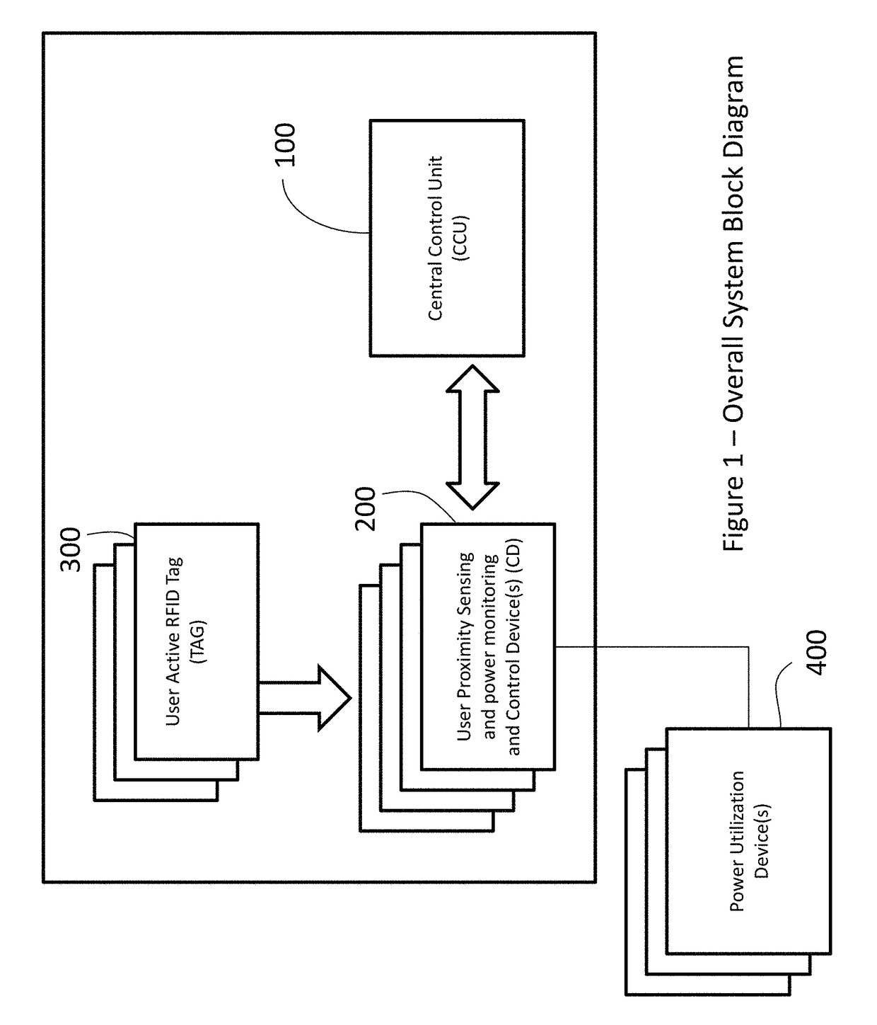
[0017]The system as described in FIG. 1 intends to monitor a series of proximity tags sensed through proximity energy monitoring and control devices (CDs) attached to lighting fixtures and / or electrical plugs distributed ubiquitously and regularly in a grid like pattern throughout a facility. The system takes advantage of the natural grid like pattern formed from the typical layout of lighting fixtures, wall plugs, wall switches or other sensing devices distributed thro...


PUM


Abstract

The invention pertains to a method and system which utilizes individual lighting fixtures and electrical plug controls to provide a rigorous and ubiquitous grid of sensors within or around a facility or facilities. The system utilizes a variety of parameters at the tag, lighting and plug controllers and central processor level to provide unique location and tracking information on objects, equipment, and personnel in the facility. The unique aspects of the system provide higher spatial and temporal accuracy and the ability to track high spatial densities of devices.

Description

CROSS-REFERENCE TO RELATED APPLICATIONS[0001]This application is a continuation-in-part of, and claims priority to U.S. Nonprovisional application Ser. No. 14 / 011,565, entitled “Method and System for utilizing a device's user location to monitor and control the device power usage” and filed on Aug. 28, 2013, which claims priority to U.S. Provisional Application Ser. No. 61 / 694,113, entitled “Method and System for utilizing a device's user location to monitor and control the device power usage,” filed Aug. 28, 2012. This application further claims priority to U.S. Provisional Application Ser. No. 62 / 261,656, entitled “Method and System for utilizing a device's user location to monitor and control the device power usage” and filed Dec. 1, 2015.BACKGROUND OF THE INVENTION[0002]The ability to accurately establish user or equipment location in a building or complex of buildings enables a variety of value added applications. A number of Real Time Location Service (RTLS) or similar systems...

Claims


Application Information

Patent Timeline
Patent Type & Authority Patents(United States)
IPC IPC(8): G06F1/26G06F1/32G06F1/28G05B19/042
CPCG06F1/3231G05B19/042G06F1/26G06F1/3203G06F1/325G06F1/28G05B2219/2639G05B15/02G05B2219/2642
Inventor FITCH, JOHN EDWARDSTEWARD, JAMES M.HOLLAND, II, JOHN D.
Owner BCP CONTROLS
Why Eureka
Try Eureka