
Image forming apparatus for reducing misdetections

a technology of image forming apparatus and misdetection, applied in the direction of electrographic process apparatus, instruments, optics, etc., can solve the problems of affecting the service life of the photosensitive layer, the photosensitive layer is susceptible to mechanical external force, and the exposed portion suddenly wears out, so as to reduce the misdetection of residual service life.

Active Publication Date: 2019-01-22
CANON KK
View PDF8 Cites 0 Cited by
  • Summary
  • Abstract
  • Description
  • Claims
  • Application Information

AI Technical Summary

Benefits of technology

The patent aims to prevent incorrect detection of the end-of-life of a photosensitive member caused by exposure memory.

Problems solved by technology

However, even in a photosensitive member having a cured layer as a surface layer, surface wear cannot be avoided completely.
The photosensitive layer is susceptible to mechanical external force and is suddenly worn out from the exposed portion.
Then, the charge cannot be maintained and the photosensitive layer reaches the end of service life.
However, it has turned out that a direct current which flows through a photosensitive member is affected by exposure memory of the photosensitive member.
As a result, in the photosensitive member in which exposure memory occurs, an extra direct current will be detected and, therefore, misdetection of the film thickness will occur.

Method used


Image

  • Image forming apparatus for reducing misdetections
  • Image forming apparatus for reducing misdetections
  • Image forming apparatus for reducing misdetections

Examples


first embodiment

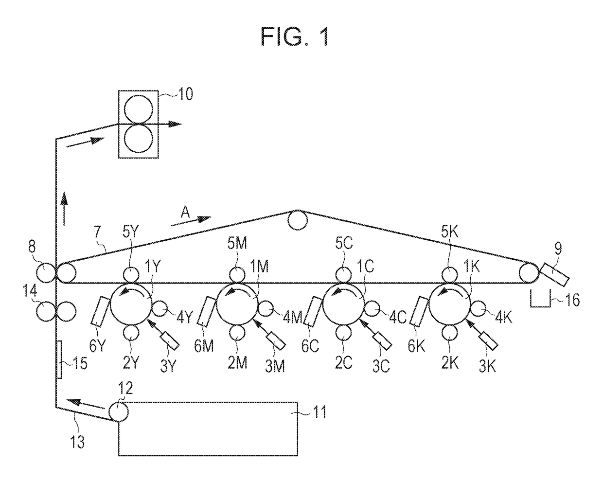
[0030]Regarding a process speed of the photosensitive member 1 during direct current detection in the present embodiment, a method of changing from a process speed during of ordinary image formation will be described.

[0031]First, detection of a film thickness of the photosensitive member 1 in the present disclosure will be described.

Mechanism of Detection of Film Thickness of Photoconductor 1

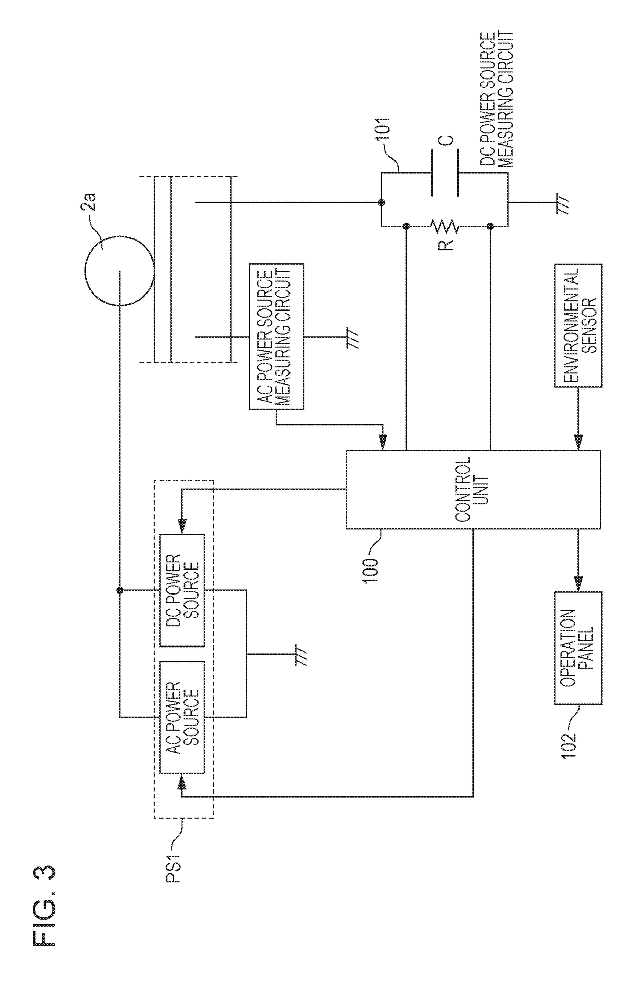
[0032]FIG. 4 illustrates a relationship between the film thickness of the photosensitive member 1 and the direct current I which flows when a direct current voltage is applied to the photosensitive member 1 from the charging roller 2a. A relationship expressed by Expression 1 is established between a surface potential V0 of the photosensitive member 1 provided by the charging roller 2a and a film thickness d of the photosensitive layer of the photosensitive member 1. The film thickness d is a distance from the surface of the photosensitive layer to a surface of a conductive base 1e. In Expressio...

second embodiment

[0043]The present embodiment is a configuration with respect to exposure memory of a photosensitive member 1 which is highly likely to occur when a photosensitive member is replaced or a drum cartridge is replaced. By referring to the use history of the photosensitive member 1, it is possible to automatically change to a charge travel distance mode. That is, when the photosensitive member (or the drum cartridge) is replaced, the charge travel distance mode is automatically employed instead of employing the direct current detection mode in a predetermined period from the replacement and start of use of the photosensitive member. The control unit 100 detects attachment and removal of the photosensitive member to and from an image forming apparatus. Examples of the detection methods may include a method of providing memory in the drum cartridge and detecting attachment and removal by contact with the image forming apparatus, and a method of providing sensor for detecting attachment and...


PUM


Abstract

After a predetermined period elapses since the start of use of a photosensitive member, if a calculated value calculated from a detection current between a charging unit and a photosensitive member is out of a predetermined range, a determining unit does not perform determination using a currently calculated value and, if the calculated value is within the predetermined range, the determining unit performs determination using the currently calculated value.

Description

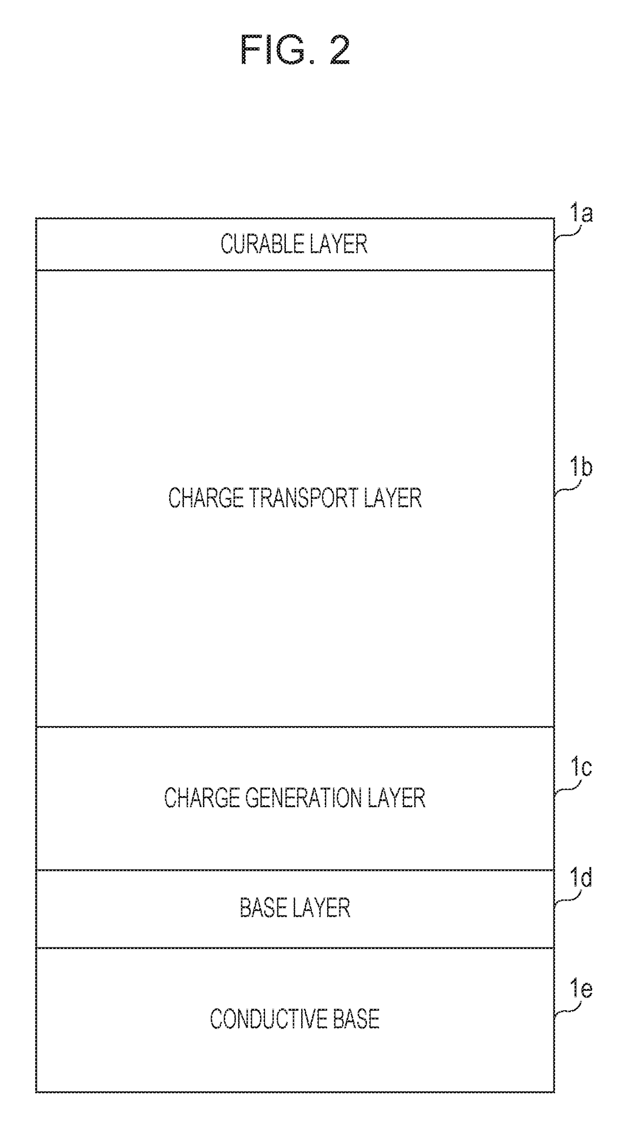
BACKGROUNDField of the Disclosure[0001]The present disclosure, relates to an image forming apparatus which employs an electrophotographic process or an electrostatic recording process, such as a copier and a laser printer.Description of the Related Art[0002]As an electrophotographic photosensitive member (hereinafter, referred to as “photosensitive member”), a photosensitive member in which a photosensitive layer (an organic photosensitive layer) using an organic material as a photoconductive substance (a charge generation material and a charge transport material) is provided on a metal substrate is widely used for its low cost and high productivity. As a photosensitive member, a photosensitive member which includes a laminated photosensitive layer in which a charge generation layer containing a charge generation material of a photoconductive dye or a photoconductive pigment, and a charge transport layer containing a charge transport material of a photoconductive polymer or a photoc...

Claims


Application Information

Patent Timeline
Patent Type & Authority Patents(United States)
IPC IPC(8): G03G15/00G03G21/20G03G15/20
CPCG03G15/5037G03G15/80G03G2215/00632G03G21/20G03G15/2053G03G15/0266G03G15/0283
Inventor HIROTA, SHINGO
Owner CANON KK
Learn More