Antenna device for emitting and receiving electromagnetic waves

Pending Publication Date: 2022-10-27
ALPS ALPINE CO LTD
View PDF0 Cites 0 Cited by
  • Summary
  • Abstract
  • Description
  • Claims
  • Application Information

AI Technical Summary

Problems solved by technology

Emitting electromagnetic waves from a radar antenna and reflecting them towards an object and additi

Method used


Image

  • Antenna device for emitting and receiving electromagnetic waves
  • Antenna device for emitting and receiving electromagnetic waves
  • Antenna device for emitting and receiving electromagnetic waves

Examples


Embodiment Construction

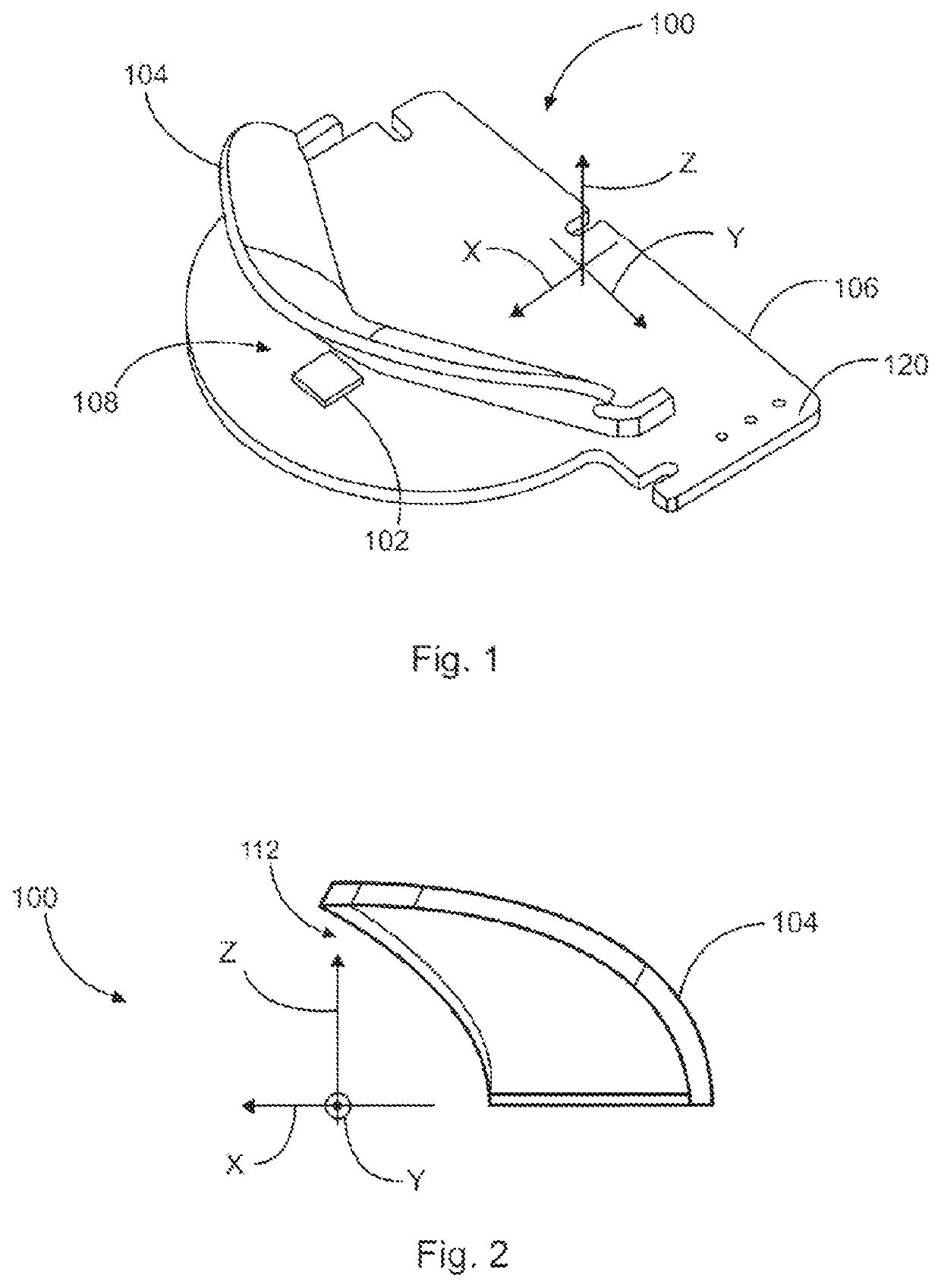
[0076]FIG. 1 shows an antenna device 100 comprising an antenna element 102 for emitting and receiving electromagnetic waves, as e.g. radar signals. Furthermore, the antenna device 100 comprises a reflector 104 for reflecting the electromagnetic waves emitted from the antenna element 102. In addition, the antenna device 100 comprises a substrate 106 on which the antenna element 102 and the reflector 104 are positioned. In particular, the antenna element 102 and the reflector 104 are attached to a surface 120 of the substrate 106. In addition, the substrate 106 has a main extension plane 108 extending along a horizontal direction Y and a lateral direction X. In addition, a vertical direction Z extends perpendicular to the horizontal direction Y and the lateral direction X and, thus, perpendicular to the main extension plane 108 of the substrate 106. In other words, the vertical direction Z is oriented perpendicular to the surface 120 of the substrate 106.

[0077]Furthermore, the reflect...


PUM


Abstract

An antenna device (100) includes an antenna element (102) for emitting and receiving electromagnetic waves, a reflector (104) for reflecting the electromagnetic waves emitted from the antenna element (102), and a substrate (106) on which the antenna element (102) and the reflector (104) are positioned. The substrate (106) defines a main extension plane (108) extending along a horizontal direction (Y) and a lateral direction (X), wherein a vertical direction (Z) extends perpendicular to the horizontal direction (Y) and the lateral direction (X), and thus perpendicular to the main extension plane (108). The reflector (104) has a concave shape (112) in the vertical direction (Z) thereby spatially narrowing in the vertical direction (Z) the electromagnetic waves emitted by the antenna element (102), and has a convex shape (110) in the horizontal direction (Y) thereby spatially widening in the horizontal direction (Y) the electromagnetic waves emitted by the antenna element (102).

Description

CLAIM OF PRIORITY[0001]This application is a Continuation of International Application No. PCT / IB2021 / 050663 filed on Jan. 28, 2021, which claims benefit of European Patent Application No. 20154703.1 filed on Jan. 30, 2020. The entire contents of each application noted above are hereby incorporated by reference.BACKGROUND OF THE INVENTION1. Field of the Invention[0002]The present invention is directed to an antenna device for emitting and receiving electromagnetic waves, an automotive sensor for detecting a movement of an object, a vehicle with a sensor for detecting a movement of an object and a method for detecting a movement of an object relative to a sensor.2. Description of the Related Art[0003]Emitting electromagnetic waves from a radar antenna and reflecting them towards an object and additionally receiving the reflected electromagnetic waves with the same radar antenna is a common problem. Therefore, a variety of different reflectors and horn antennas exist, but specific app...

Claims


Application Information

Patent Timeline
IPC IPC(8): H01Q3/44H01Q15/14H01Q1/32
CPCH01Q3/44H01Q15/14H01Q1/3233H01Q1/3283H01Q15/16H01Q1/3241G01S2013/93275G01S13/56H01Q19/132
Inventor WAERN, MARTENCARLSSON, MARTIN
Owner ALPS ALPINE CO LTD
Why Eureka
Try Eureka