Laser scanner controlling device, laser scanner controlling method, and laser scanner controlling program

a laser scanner and control device technology, applied in surveying and navigation, distance measurement, instruments, etc., can solve the problems of long work time, inconvenient use, and inability to detect sunlight, so as to reduce the detection of sunligh

Active Publication Date: 2019-07-16
KK TOPCON
View PDF11 Cites 0 Cited by
  • Summary
  • Abstract
  • Description
  • Claims
  • Application Information

AI Technical Summary

Benefits of technology

[0005]In view of these circumstances, the present invention is to provide a technique for reducing detection of sunlight as noise in obtaining point clouds using a laser scanner.
[0007]According to the first aspect of the present invention, misdetection of sunlight as measured light is greatly reduced. As the conditions restricting laser scanning, the following conditions may be described.
[0013]According to the present invention, a technique for reducing detection of sunlight as noise in obtaining point clouds using a laser scanner is provided.

Problems solved by technology

In the case of obtaining three-dimensional point cloud position data by using a laser scanner, noise is undesirably contained in a point cloud.
There may be various sources of noise in point clouds, but in cases of outdoor measurement, the sun is the primary noise source.
However, each of these methods requires performing some processing steps after the point clouds are generated, and each of these methods takes long work time and is complicated.

Method used


Image

  • Laser scanner controlling device, laser scanner controlling method, and laser scanner controlling program
  • Laser scanner controlling device, laser scanner controlling method, and laser scanner controlling program
  • Laser scanner controlling device, laser scanner controlling method, and laser scanner controlling program

Examples


example of processing

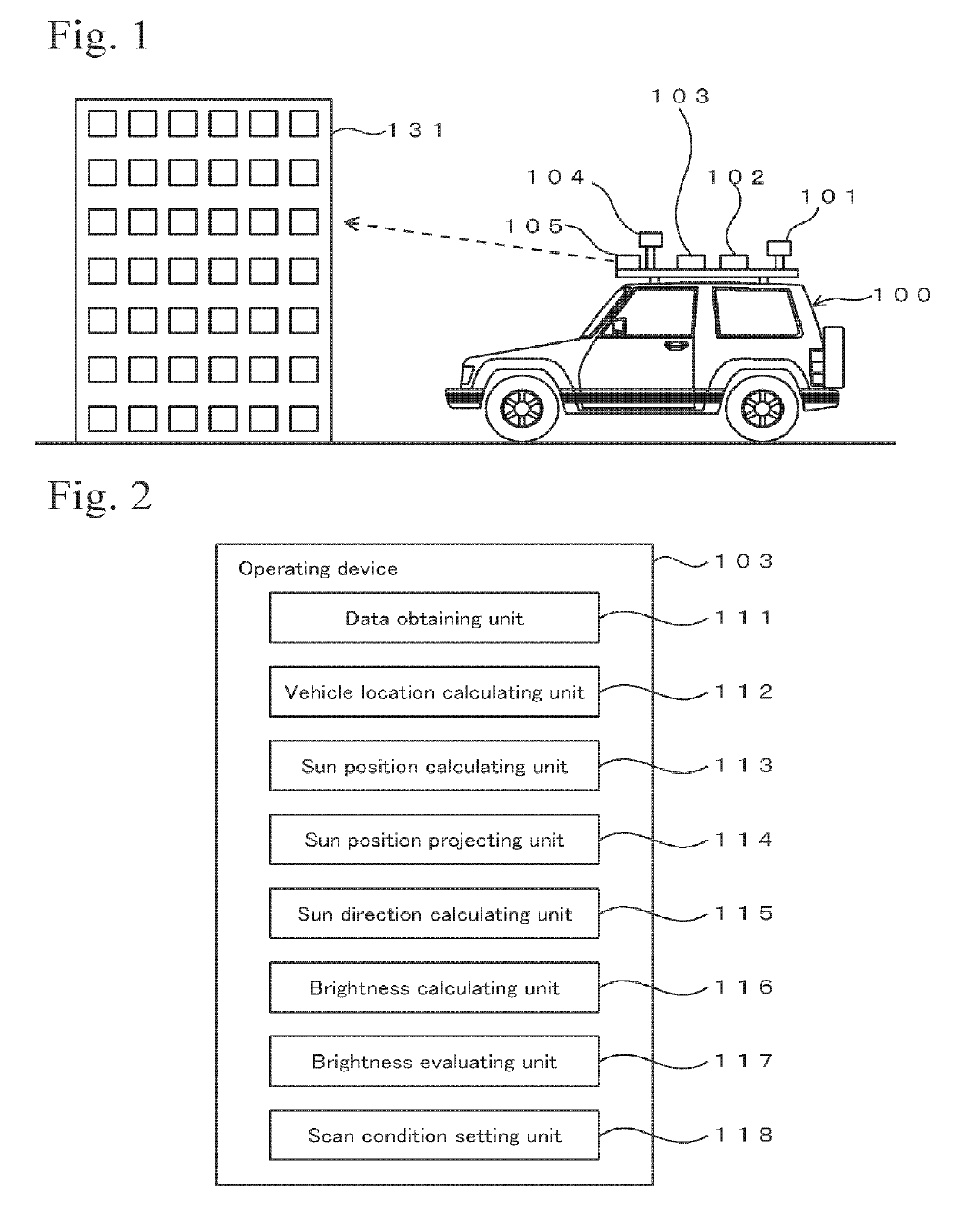
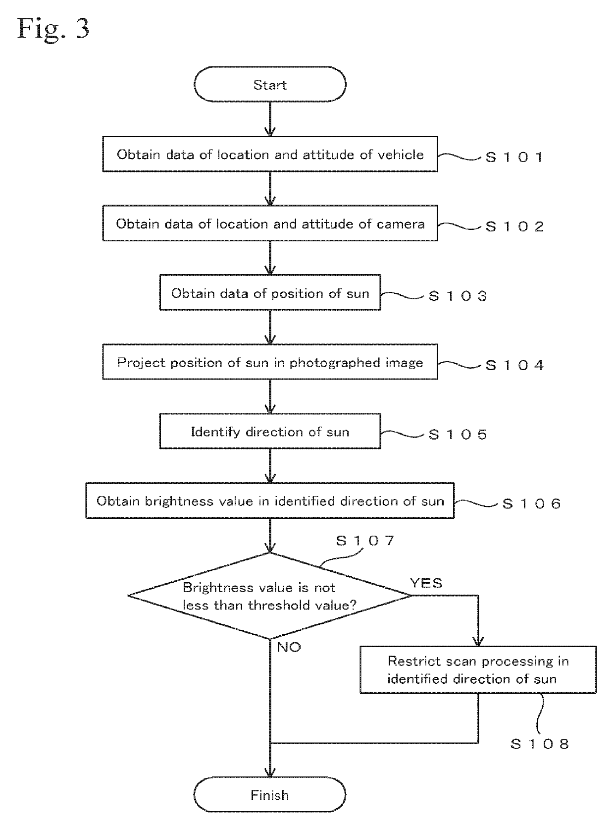
[0028]FIG. 3 shows an example of a processing procedure. Programs for executing the processing shown in FIG. 3 are stored in an appropriate storage medium and are executed by the hardware shown in FIG. 2. When the processing starts, first, data of location and attitude of the vehicle at time “t” is obtained (step S101). The data of the location of the vehicle is calculated by the vehicle location calculating unit 112, and the data of the attitude of the vehicle is obtained from the IMU 102. The time “t” is set at a predetermined time interval such as each 0.2 seconds (operation at 5 Hz).

[0029]Since the exterior orientation parameters (position and attitude) of the camera 104 relative to the vehicle 100 are already known, by determining the location and the attitude of the vehicle, data of the location and the attitude of the camera 104 is obtained (step S102). Then, the position data of the sun at time “t” is obtained (step S103). The position data of the sun is calculated by the su...


PUM


Abstract

Detection of sunlight as noise is avoided in obtaining point clouds by using a laser scanner. A laser scanner controlling device includes a sun direction calculating unit 115, a brightness measuring unit 116, and a scan condition setting unit 118. The sun direction calculating unit 115 calculates the direction of the sun. The brightness measuring unit 116 measures the brightness of an image that contains the direction of the sun. The scan condition setting unit 118 sets a condition for restricting laser scanning in the direction of the sun when the brightness is not less than a predetermined threshold value.

Description

BACKGROUND OF THE INVENTIONTechnical Field[0001]The present invention relates to a technique for obtaining three-dimensional point cloud position data by using a laser scanner (LIDAR).Background Art[0002]Technology for a MMS (Mobile Mapping System) is publicly known (for example, refer to Japanese Unexamined Patent Application Laid-Open No. 2012-242317). In the MMS, a vehicle is equipped with a GNSS unit, a camera, a laser scanner, an IMU (Inertial Navigation Unit), etc., and the vehicle obtains three-dimensional data and images of the surroundings while travelling, whereby a three-dimensional model of the travelling environment is obtained. The three-dimensional data that is obtained by the MMS may be used for city planning, civil engineering work, disaster prevention plans, etc.[0003]In the case of obtaining three-dimensional point cloud position data by using a laser scanner, noise is undesirably contained in a point cloud. Therefore, it is essential to effectively reduce and rem...

Claims


Application Information

Patent Timeline
Patent Type & Authority Patents(United States)
IPC IPC(8): G01C3/08G01S17/89G01S7/497G01S17/02G01S17/42G01S7/486G01S7/491G01S7/4912G01S17/86
CPCG01S17/89G01S7/486G01S17/42G01S7/4912G01S17/023G01S7/497G01S17/86
Inventor SASAKI, YOUITO, TADAYUKI
Owner KK TOPCON
Why Eureka
Try Eureka