Ideal switch bridgeless PFC

a switch bridge and bridgeless technology, applied in the field of ideal switch bridgeless pfc, can solve the problems of increased resistance loss, extra choke, and increased resistance loss, and achieve the effect of reducing the cost of installation, and increasing the cost of installation

Active Publication Date: 2019-01-22
ROMPOWER TECH HLDG LLC
View PDF1 Cites 3 Cited by
  • Summary
  • Abstract
  • Description
  • Claims
  • Application Information

AI Technical Summary

Benefits of technology

[0006]Shown in FIG. 1, is a bridgeless PFC topology that replaces both bottom low frequency diodes of the bridge with switches and replaces the top low frequency diodes with high frequency diodes. Shown in this figure is input AC voltage source (2) with phase connection as (1)(also referred as Vacp in this document) and neutral connection as (11)(also referred as Vacn in this document), input filtering capacitors (3,10), high frequency diodes (5,8), input chokes (4,9), output capacitor (12), MOSFETs (6,7) as switches, and output voltage (13,14). In order for reduced common mode switching two inductors (4) and (9) are used. To hold the common (13) steady, capacitors (3) and (10) are used on the other side of the chokes. This topology is very good in terms of semiconductor drops. During an “On” in either polarity, it has two switches of drop (both switches (6) and (7) are on). During the off the switch that is connected to the choke on the more positive of the input line (phase or neutral) is turned off. When phase (1) is more positive than neutral (11) switch (6) is turned off. When neutral is more positive than phase switch (7) is turned off. The remaining switch during the off remains on. During the off, the drop is a high frequency diode and the other switch. The switch that is on all the time in one polarity has only the high frequency ripple current. The DC component (low frequency AC component) flows in the inductor in parallel with it. Since both MOSFET switches have their sources connected to common in this topology, they are easy to drive. Even though this topology has excellent characteristics for the switches and diodes, it does have one drawback. It uses two chokes, each of them must be designed magnetically to handle the peak power and ripple. Each choke must be designed to withstand the full volt seconds since each choke is used on different polarities as the main choke while the other choke is bypassed. In addition, both chokes have the line input low frequency current in both polarities. That means that even though only one choke has core losses and ripple in one polarity both chokes have the low frequency AC line current resistive losses. This extra choke adds resistive losses, costs, and extra space.

Problems solved by technology

Even though this topology has excellent characteristics for the switches and diodes, it does have one drawback.
That means that even though only one choke has core losses and ripple in one polarity both chokes have the low frequency AC line current resistive losses.
This extra choke adds resistive losses, costs, and extra space.
The only difficulty would be the driving of the bi-directional switch using a floating drive (21).
This has to be carefully done in order to be able to bias the drive circuitry correctly, since normal boost strapping methods will not work.

Method used


Image

  • Ideal switch bridgeless PFC
  • Ideal switch bridgeless PFC
  • Ideal switch bridgeless PFC

Examples


Embodiment Construction

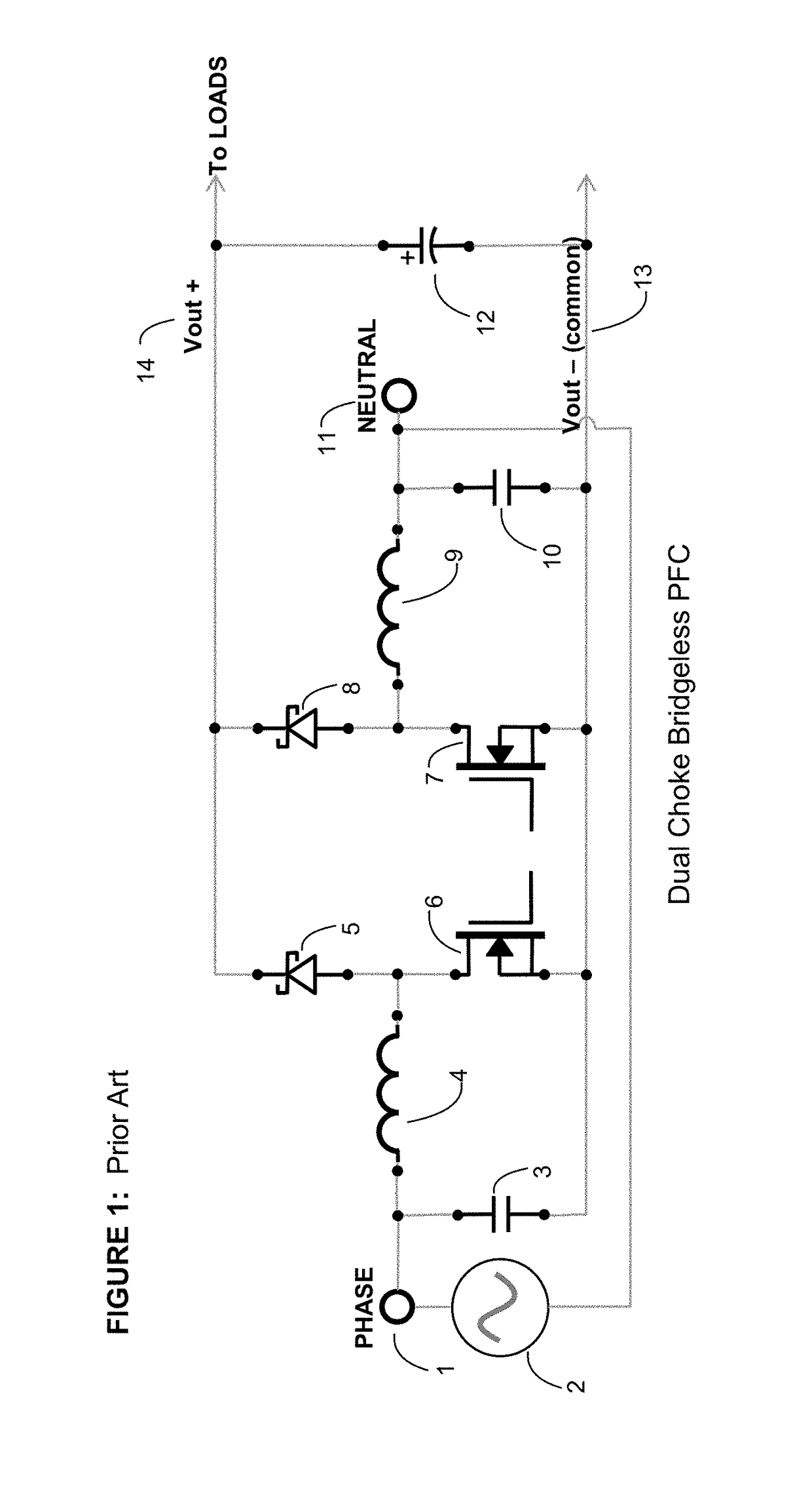
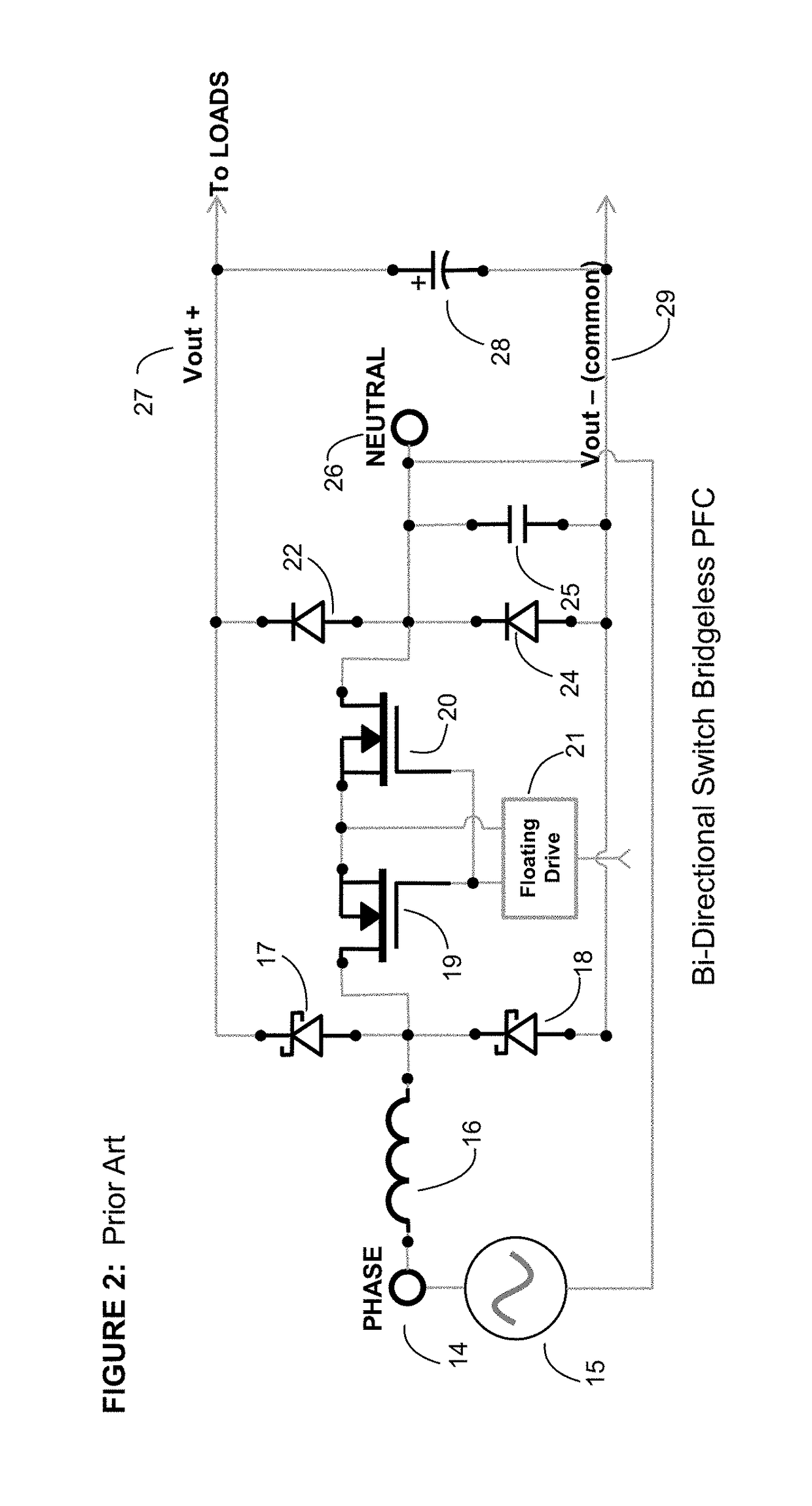
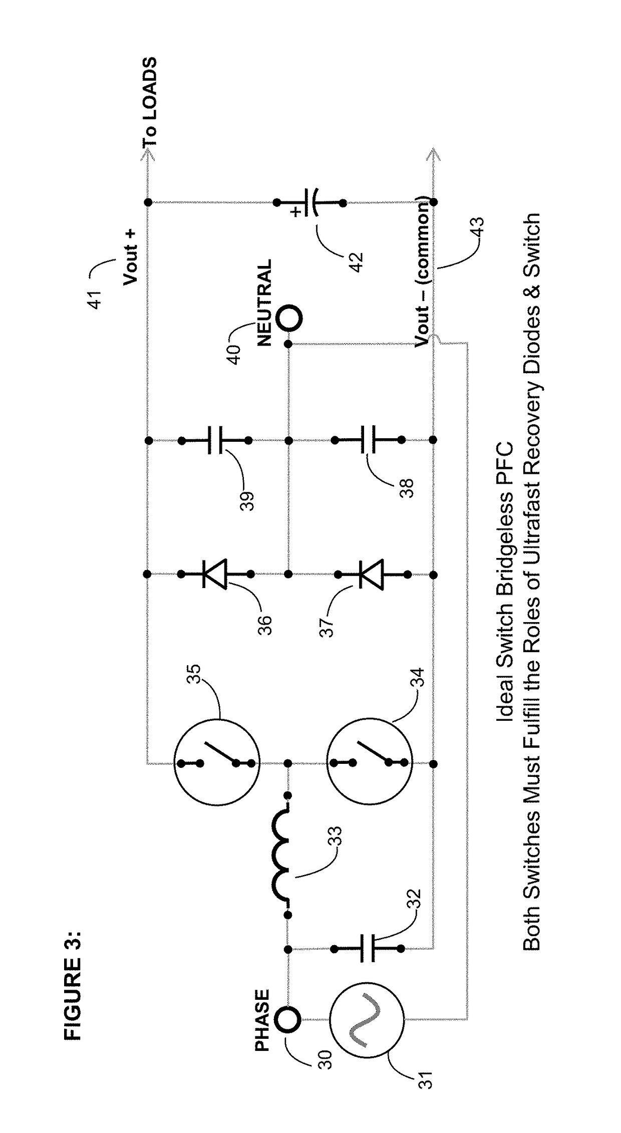
Ideal Switch Topologies

[0050]FIG. 3, shows a topology where the left side of the bridge is replaced by switches (34) and (35). The neutral is held steady compared to common on the right side by the use of two capacitors (38) and (39). Capacitor (32) also can be used for this. A capacitor from phase to Vout can also be used (not shown). In this topology the switches must do the work of both boost switch and diode depending on the polarity of the input line. The drop during an on and off will be a switch and a low frequency diode. Unfortunately most modern day switches cannot fulfill both roles at the same time if the converter is run in continuous conduction mode. Reverse recovery losses in the body diode of the switch fulfilling the diode role would overwhelm the efficiency savings. Even though this topology has the best semiconductor drops it must be modified in order to use silicon MOSFETs due to this problem. Shown in FIG. 4, is a modification where the top switch (35) and bottom...


PUM


Abstract

Ideal switch bridgeless PFC topologies are presented with the purpose of increasing the efficiency in power factor correction circuits and inverter applications. The topology also leverages the new GaN switches that are available. This patent offers also a very good solution for the Zero crossing distortion problem improving greatly the THD both in power factor correction and inverter applications.

Description

RELATED APPLICATION / CLAIM OF PRIORITY[0001]This application is related to and claims priority from U.S. provisional application Ser. No. 62 / 236,887, filed Oct. 3, 2015, and which provisional application is incorporated by reference herein.INTRODUCTION[0002]Efficiency is one of the most important parameters in power supplies. In typical power factor correction boost topologies the input AC voltage is first rectified then processed by a boost converter. Since the boost also has a rectification function there are topologies that take advantage of this so that a portion of the input bridge is replaced by the existing boost converter. This normally saves a bridge diode drop increasing the efficiency of the converter. Topologies where a portion of the input AC bridge is replaced by the boost converter are called bridgeless PFC's. There are difficulties with all of them. Presented in this paper is one combination that when ideal switches similar to GaN are introduced, will eliminate the ma...

Claims


Application Information

Patent Timeline
Patent Type & Authority Patents(United States)
IPC IPC(8): H02M1/42
CPCH02M1/4208H02M1/4225Y02B70/1483Y02B70/126Y02B70/10Y02P80/10H02M1/0085
Inventor JITARU, IONELDAVILA, MARCO ANTONIOTAMAS, COSMIN ANDREI
Owner ROMPOWER TECH HLDG LLC
Why Eureka
Try Eureka