Resin molded component and method for manufacturing resin molded component

a technology manufacturing methods, which is applied in the direction of vehicle components, signalling/lighting devices, lighting and heating apparatus, etc., can solve the problems of reducing the productivity of resin molded components, the mechanism of mold complex, and the inability to apply techniques, so as to reduce the surface roughness of the designed surface and restrict the effect of productivity reduction

Active Publication Date: 2019-01-29
KOITO MFG CO LTD
View PDF10 Cites 0 Cited by
  • Summary
  • Abstract
  • Description
  • Claims
  • Application Information

AI Technical Summary

Benefits of technology

[0004]A crystalline resin material is raised as a resin material for the resin molded piece. The crystalline resin has good flow properties and tends to transfer easily a tiny scratch or a cut mark on a molding surface of a mold to a surface of a molded piece. Because of this, when a crystalline resin is used as a resin material, compared with a case where a non-crystalline resin is used, the molding surface of the mold needs to be polished so as to make the molding surface smooth, that is, to reduce the roughness of the mold.
[0005]When the surface roughness of the mold is reduced, the adhesion properties of the mold to the resin material is increased, producing a phenomenon in which a molded piece sticks to the fixed mold half when the mold is opened. This requires the resin molded piece to be removed from the mold with great care taken to make a molded surface flawless, reducing the productivity of the resin molded piece. According to the technique described in Patent Literature 1, a locking portion is formed on a resin molded piece, and a slide core which is in engagement with the locking portion is moved to restrict the molded piece from sticking to a fixed mold half side. However, this makes the mechanism of the mold complex, and there can be a case where depending upon the shape of a resin molded piece, the technique cannot be applied.
[0006]The invention has been made in view of these situations, and an object thereof is to provide a resin molded piece of a crystalline resin which can suppress reduction of the productivity and reduce the surface roughness of a designed surface and a fabrication method of the resin molded piece.
[0008]According to this aspect, not only the mirror surface portion of the designed surface but also the non-designed surface has the surface roughness Ra of 0.5 μm or smaller. In fabricating the resin molded piece, when the mold is opened, due to the surface roughnesses Ra, the force with which the mold pulls the non-designed surface of the resin molded piece becomes relatively strong, thereby making it possible to restrict the designed surface from being kept sticking to the mold.
[0010]According to this aspect, the draft angle of the second mold at the projecting portion becomes smaller than the draft angle of the first mold at the projecting portion. Because of this, the force with which the second mold pulls the projecting portion becomes relatively strong, thereby making it possible to restrict the generation of a so-called cavity sticking.
[0012]According to the invention, it is possible to provide the resin molded piece of a crystalline resin which can reduce the surface roughness of the designed surface while restricting the reduction in productivity and the method for fabricating the resin molded piece.

Problems solved by technology

This requires the resin molded piece to be removed from the mold with great care taken to make a molded surface flawless, reducing the productivity of the resin molded piece.
However, this makes the mechanism of the mold complex, and there can be a case where depending upon the shape of a resin molded piece, the technique cannot be applied.

Method used


Image

  • Resin molded component and method for manufacturing resin molded component
  • Resin molded component and method for manufacturing resin molded component
  • Resin molded component and method for manufacturing resin molded component

Examples


Embodiment Construction

[0023]Hereinafter, like reference numerals will be given to like or equivalent constituent elements or members which are shown in the individual drawings, so that the repetition of similar descriptions will be omitted as required. Dimensions of members in the drawings are magnified or reduced as required to facilitate the understanding of what is illustrated therein. In the drawings, part of members which is considered to be unimportant to illustrate an embodiment of the invention will be omitted from illustration.

[0024]Firstly, what brought the inventor to a resin molded piece and a fabrication method therefor will be described.

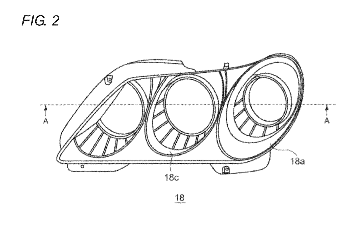
[0025]An extension of a vehicle lamp is provided near a light source to be heated to high temperatures, and therefore, the extension is required to hold a relatively high heat resistance. Because of this, there has been an increasing tendency that high-heat PC (polycarbonate) or PBT (polybutylene terephthalate) is used as a resin material for the extension. ...


PUM

PropertyMeasurementUnit
roughnessesaaaaaaaaaa
angleaaaaaaaaaa
angleaaaaaaaaaa

Abstract

A resin molded piece is made from a crystalline resin and is molded by filling a molding space 36 which is defined between a movable mold 32 and a fixed mold 34 with the resin. The resin molded piece has a designed surface 18a on to which a surface of the movable mold 32 is transferred and a non-designed surface 18b on to which a surface of the fixed mold 34 is transferred. The designed surface 18a includes a mirror surface portion 18a. Center line average roughnesses Ra of the mirror surface portion 18c and the non-designed surface 18b are both 0.5 μm or smaller. According to the resin molded piece and a fabrication method therefor, the surface roughness of the designed surface can be reduced while restricting a reduction in productivity.

Description

CROSS-REFERENCE TO RELATED APPLICATION[0001]The present application claims the benefit of priority of Japanese Patent Applications No. 2014-083664, filed on Apr. 15, 2014, which is incorporated herein by reference.TECHNICAL FIELD[0002]The present invention relates to a resin molded piece and a resin molded piece fabricating method.BACKGROUND ART[0003]There may be a case where a resin molded piece is required to have mirror properties at least part of a surface thereof from the viewpoint of design. As one of methods of enhancing the mirror properties of a resin molded piece, it is known to reduce the surface roughness of a mold which corresponds to a designed surface of a molded piece. JP-A-2008-126446 proposes a resin molded piece fabrication method which uses such a mold.SUMMARY OF THE INVENTION[0004]A crystalline resin material is raised as a resin material for the resin molded piece. The crystalline resin has good flow properties and tends to transfer easily a tiny scratch or a c...

Claims


Application Information

Patent Timeline
Patent Type & Authority Patents(United States)
IPC IPC(8): B29C45/40F21S41/50B29C45/37B60Q1/04B29K101/12
CPCB29C45/37F21S41/50B29K2995/0072B29K2995/0041B29K2101/12
Inventor NAKAMURA, MASATOKOHATA, TAKAHIROIKEDA, TOSHIMASA
Owner KOITO MFG CO LTD
Why Eureka
Try Eureka