
Sealed bearing assembly

a bearing assembly and seal technology, applied in the direction of mechanical equipment, engine components, rotary machine parts, etc., can solve the problems of increasing the temperature of the rolling bearing, increasing the friction between the two, and the seal torque cannot be significantly reduced, so as to prevent the wear of the seal lip, reduce the seal torque to practically zero, and facilitate the formation

Active Publication Date: 2019-01-29
NTN CORP
View PDF40 Cites 3 Cited by
  • Summary
  • Abstract
  • Description
  • Claims
  • Application Information

AI Technical Summary

Benefits of technology

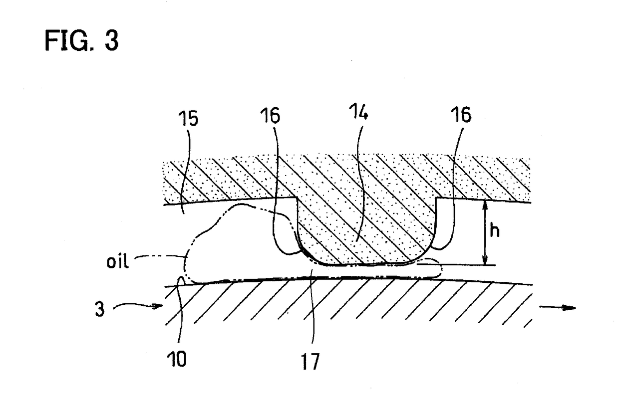
[0016]It is possible to determine the maximum diameter of foreign objects that can pass through the oil passages based on the protruding height of the protrusion. Thus, it is possible to freely determine the minimum particle diameter of foreign objects that cannot pass through the oil passages into the bearing.
[0009]An object of the present invention is to reduce torque and increase the maximum speed, of a sealed bearing assembly, while preventing entry of foreign objects larger in diameter than predetermined threshold.

Problems solved by technology

Also, the friction due to such slide contact increases the temperature of the rolling bearing.
The higher the temperature of the bearing, the more strongly the seal lips tend be pressed against the seal sliding surfaces due to an increased pressure difference between the interior space of the bearing and the exterior of the bearing, thus further increasing the friction therebetween.
However, since it is difficult to significantly reduce this area, the seal torque cannot be significantly reduced, either.
However, as the bearing is operated continuously, the oil temperature rises and its viscosity decreases, thus making the formation of oil film increasingly difficult.
Also, the higher the operating speed of the bearing, the higher the peripheral speed of the seal sliding surface relative to the seal lip, so that a larger amount of heat is generated due to friction between the seal lip and the seal sliding surface, resulting in an increased oil temperature and faster wear of the seal lip.
Thus, the maximum speed, i.e., maximum rotational speed, of the sealed bearing disclosed in JP Patent Publication 2007-107588 A is limited due to its lubricating conditions.
That is, while there is a strong demand for sealed bearings which are capable of supporting rotating parts in the drive train of an electric vehicle (EV) and capable of being operated at high speed, sealed bearings whose seal sliding surfaces are subjected to shot peening for reduced torque cannot meet this demand.
While a bearing with non-contact seal members is free of seal torque, it is difficult to precisely manage the sizes of the gaps between the seal members and bearing parts to prevent entry of foreign objects larger in diameter than a predetermined threshold.

Method used


Image

  • Sealed bearing assembly
  • Sealed bearing assembly
  • Sealed bearing assembly

Examples


specific embodiments

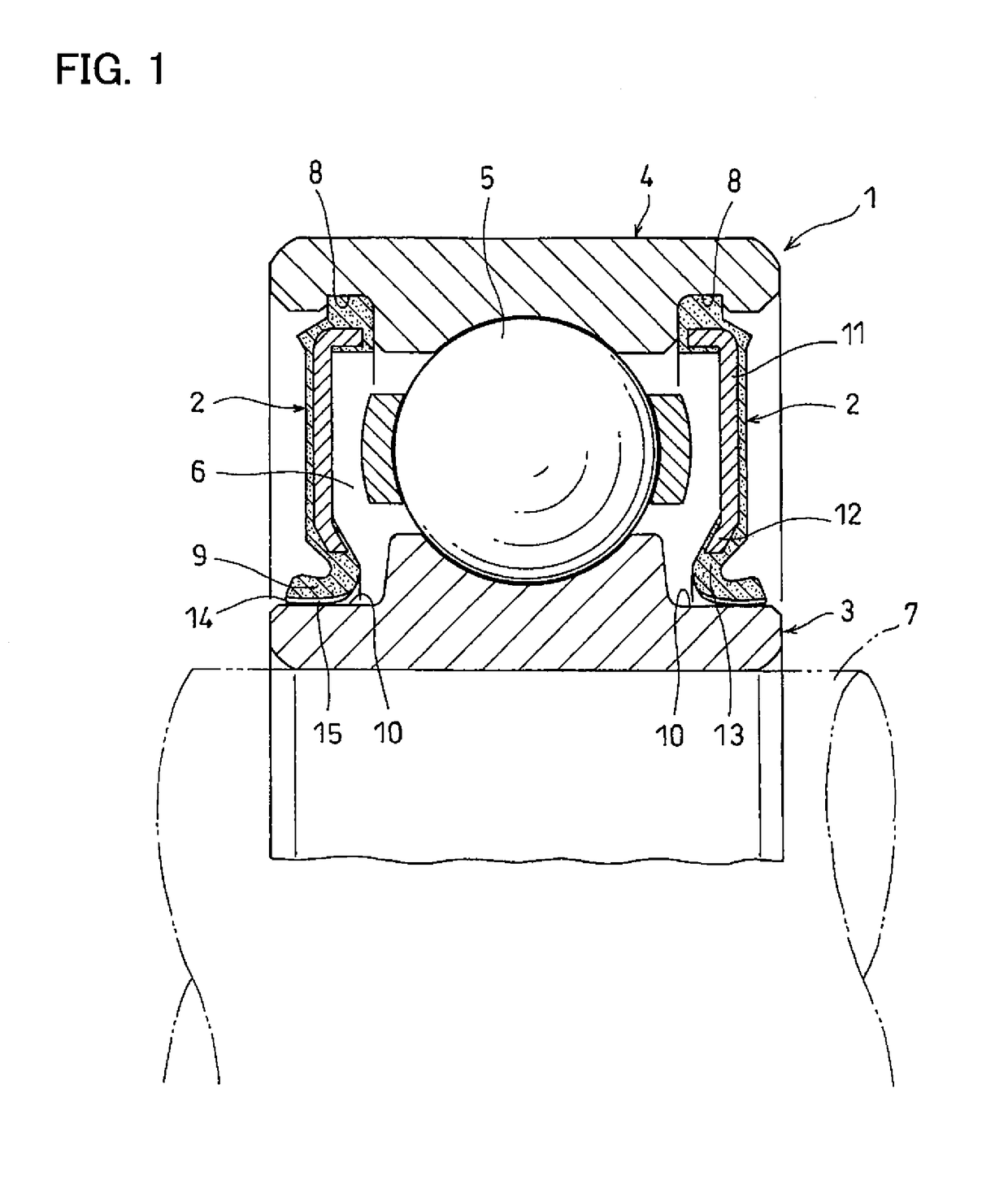
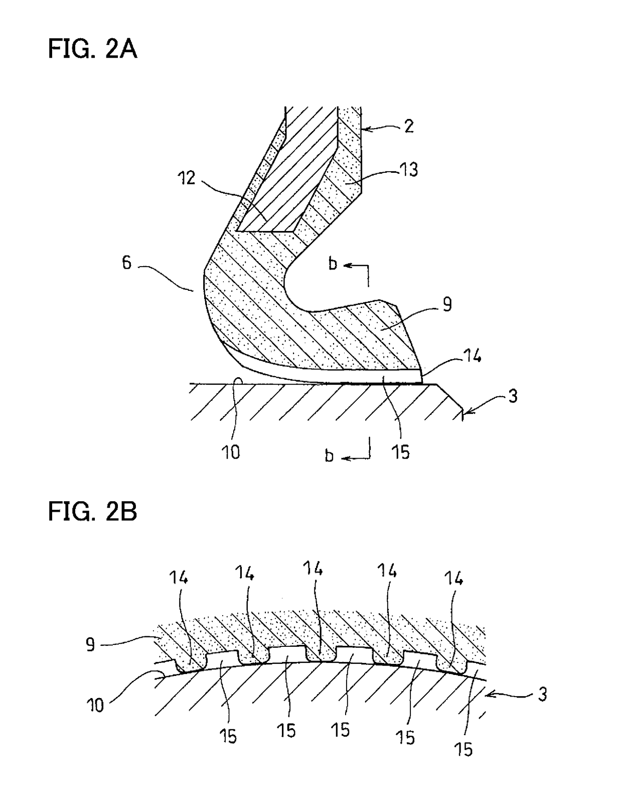
[0052]FIGS. 1-3 show a first specific embodiment of the present invention. As shown in FIG. 1, the first specific embodiment is a sealed bearing assembly including a rolling bearing 1, and seal members 2 at the respective ends of the rolling bearing 1.

[0053]The rolling bearing 1 includes an inner race 3, an outer race 4, and a plurality of rolling elements 5. The inner race 3 and the outer race 4 define an annular bearing interior space 6. The rolling elements 5 are received in the bearing interior space 6, while being disposed between the inner race 3 and the outer race 4, and are configured to revolve around the center axis of the rolling bearing 1. The rolling elements 5 are balls. Lubricating oil in the form of grease or oil from an oil bath is supplied into the bearing interior space 6.

[0054]The inner race 3 is mounted on a rotary shaft 7 to rotate together with the rotary shaft 7. The outer race 4 is mounted on a member to which a load from the rotary shaft 7 is to be applied,...


PUM

PropertyMeasurementUnit
roughness Ryaaaaaaaaaa
friction coefficientaaaaaaaaaa
heightsaaaaaaaaaa

Abstract

A sealed bearing assembly includes seal members each including a seal lip with multiple protrusions, and being arranged such that oil passages are defined between the seal lip and a seal sliding surface which is configured to slide circumferentially relative to the protrusions such that the oil passages communicate with a bearing internal space and an exterior of the bearing, and prevent passage of foreign objects having particle diameters larger than a predetermined value therethrough. The seal lip and the seal sliding surface are arranged such that, when the bearing rotates, lubricating oil in the oil passages is pulled into spaces between the seal lip and the seal sliding surface such that a fluid lubricating condition is created between the seal lip and the seal sliding surface, due to a wedge effect.

Description

CROSS REFERENCE TO RELATED APPLICATIONS[0001]This application is the National Stage of International Application No. PCT / JP2016 / 057176, filed Mar. 8, 2016 and is based on and claims the benefit of priority from Japanese Patent Application No. 2015-045800, filed on Mar. 9, 2015, Japanese Patent Application No. 2016-038993, filed on Mar. 1, 2016, and Japanese Patent Application No. 2016-044050, filed on Mar. 8, 2016, the contents of all of which are incorporated herein by reference.TECHNICAL FIELD[0002]The present invention relates to a sealed bearing assembly comprising a rolling bearing and seal members.BACKGROUND ART[0003]Foreign objects such as wear dust produced from gears exist in transmissions mounted on vehicles such as automobiles and construction machinery. Rolling bearings used in such transmissions therefore include seal members which prevent entry of foreign objects into the bearing interior space, thereby preventing premature breakage of the rolling bearings.[0004]Such s...

Claims


Application Information

Patent Timeline
Patent Type & Authority Patents(United States)
IPC IPC(8): F16C33/78F16J15/34F16C33/72F16C19/06
CPCF16C33/7823F16C19/06F16C33/726F16C33/7826F16C33/7833F16C33/7856F16J15/3428F16C2223/08F16C2300/02F16C2326/06F16J15/3408
Inventor INAMASU, KAZUNORIYOSHIMURA, YUGOWAKUDA, TAKAHIROSASAKI, KATSUAKI
Owner NTN CORP
Learn More