Door seal with two sealing planes

a sealing plane and door seal technology, applied in the direction of sealing arrangements, etc., can solve the problems insufficient sealing of the gap between the door and the frame, and affecting the sealing effect over the entire floor gap, etc., and achieve the effect of high degree of wear

Inactive Publication Date: 2019-02-05
PLANET GDZ
View PDF41 Cites 0 Cited by
  • Summary
  • Abstract
  • Description
  • Claims
  • Application Information

AI Technical Summary

Benefits of technology

[0006]A further problem consists in that, for soundproof insulation with a high degree of noise insulation, the door bottom seal has to be functionally joined into the entire sealing system of a door. In the case of known door bottom seals, this is possible only by numerous individual seals being arranged on the frame, the seals effectively sealing against the door and thereby closing gaps which arise. However, these seals, which are mounted on the frame or the door, for providing a seal between door and frame are frequently subject to wear, can be complicated to adjust during installation and are sensitive to misalignments. It is a second object of the invention to provide a door bottom seal which can be incorporated in a functionally better manner into the entire sealing system of a door and simplifies the installation.
[0045]The use can be developed by a door bottom seal with an arc portion which is arched convexly outward being used, and part of the arc portion running in the border region of the lower edge of the door, preferably in alignment with the door leaf surface above the lower edge border region. With this development, the sealing element portion which forms the second sealing line is placed into a position advantageous for the entire seal, including the seal stop plane of the door frame, and easy installation of the door bottom seal with the aim of complete sealing and simplified adjustment is achieved.

Problems solved by technology

The first problem of the devices according to the prior art thus consists in that the lowering mechanism, in particular in the event of a long lowering distance of the door bottom seal, does not move the latter on an exactly vertical path, but instead a horizontal movement component in the longitudinal direction of the seal also occurs.
This problem occurs in particular in the case of robust lowering mechanisms which are actuated by one or more pivot levers and in which linear guides having a correspondingly high degree of wear have preferably been omitted in a lowering mechanism for longevity purposes.
However, this horizontal movement component may result in air gaps laterally next to the seal, which impair the sealing effect over the entire floor gap.
However, seals which are actuated via leaf springs or seals with little lateral displacement, if any at all, also have the problem that the gap between door and frame cannot be sufficiently sealed.
A further problem consists in that, for soundproof insulation with a high degree of noise insulation, the door bottom seal has to be functionally joined into the entire sealing system of a door.
However, these seals, which are mounted on the frame or the door, for providing a seal between door and frame are frequently subject to wear, can be complicated to adjust during installation and are sensitive to misalignments.
However, a problem in this connection is that, firstly, both during the lowering operation and the raising operation of the seal, as little friction as possible between the parts moving relative to one another is desirable in order to achieve smooth-running and to reduce wear.

Method used


Image

  • Door seal with two sealing planes
  • Door seal with two sealing planes
  • Door seal with two sealing planes

Examples


first embodiment

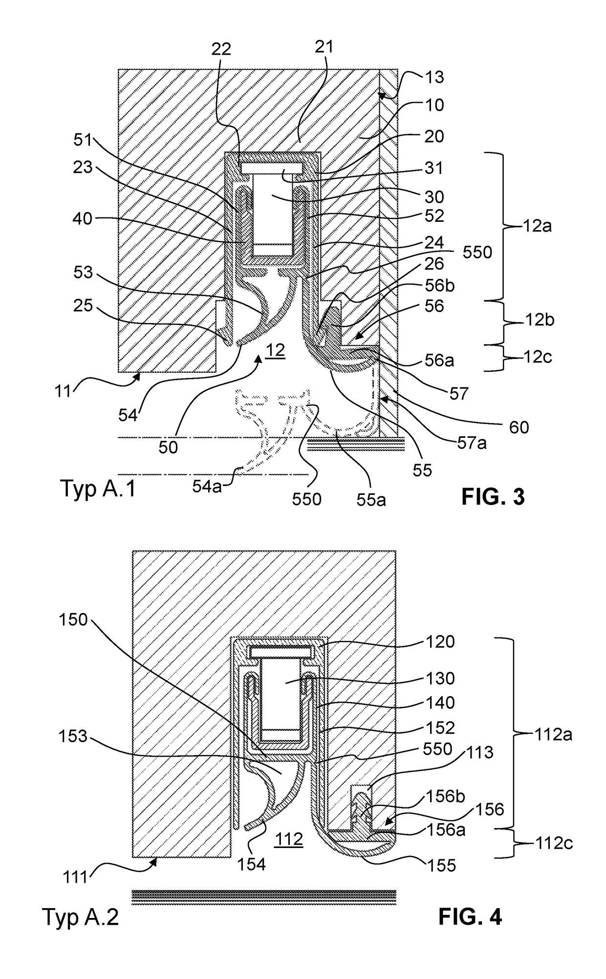
[0064]FIG. 3 shows the door bottom seal according to the invention in a fitted situation in a door. The door bottom seal is depicted in a raised state, and at the same time parts of the sealing element are also shown in a lowered state.

[0065]A door in which the door bottom seal is fitted has, in the lower edge 11 thereof, a groove 12 which is milled in the longitudinal direction of this edge. The groove 12 is designed in three stages: in a deep portion 12a, the groove is designed to be relatively narrow, a middle portion adjoining the deep portion in the direction of the door lower edge 11 is wider than said deep portion on both sides. In a lower portion 12c adjoining said middle portion 12b in turn in the direction of the lower edge of the door, the groove is widened in such a manner that it constitutes a step which extends to the frame as far as the stop surface and front door leaf surface 13 of the door. The door lower edge 11 is therefore arranged higher on the stop side than on...

second embodiment

[0079]In the second embodiment according to FIG. 4, a sealing hollow chamber profile portion 153 which likewise bears a sealing lip 154 pointing obliquely downward is formed. Said sealing hollow chamber portion 153 is of closed design and thereby has a lower degree of elasticity and exerts a higher contact pressure force for the second sealing line.

[0080]A sealing leg arc 155 extends in the same manner from the lower end of a leg arc 152 of the sealing element as far as that outer end of a fastening portion 156 which faces the door stop plane. The fastening portion 156 in turn has a horizontal base 156a in which, however, in contrast to the first embodiment, a profile portion 156b is formed centrally, said profile portion by means of corresponding barb profiles into a separate groove 113, which is arranged next to the groove 12, in the lower edge 111 of the door leaf.

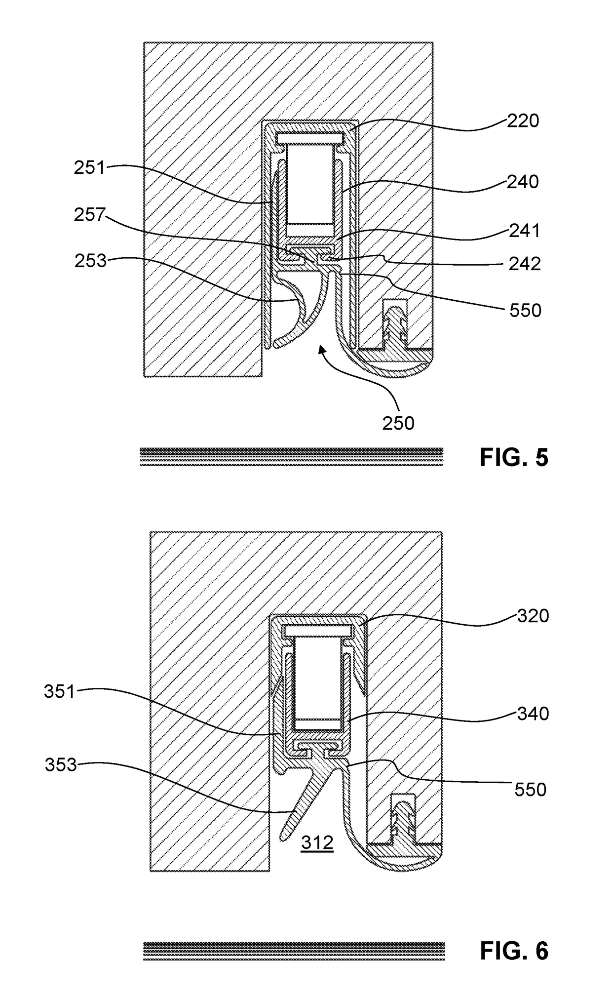
[0081]FIG. 5 shows a third embodiment of the door bottom seal according to the invention which differs from the secon...

third embodiment

[0082]Furthermore, the sealing element 250 of the third embodiment does not have any legs which point upward and are turned over at their end, as is provided in the two embodiments above for fastening the sealing element. Instead, an individual leg 251 is formed only on the side facing away from the stop side of the door, said leg not being turned over at its upper end, but rather ending with a bevel. This individual leg serves in order to produce a sealing effect between the seal receiving element 240 and the fastening element 220 and therefore to prevent bypassing of the sealing lines formed by the sealing element with the floor.

[0083]FIG. 6 shows a fourth embodiment of the door bottom seal according to the invention which differs from the previously explained, third embodiment in two functional aspects. Firstly, the fastening element 320 of this fourth embodiment is designed with shorter legs, and therefore the sealing leg 351, which is formed on one side, of the sealing element ...


PUM

PropertyMeasurementUnit
distanceaaaaaaaaaa
distanceaaaaaaaaaa
heightaaaaaaaaaa

Abstract

The door seal comprises a fixing element (20) for fixing to a door, a seal receiving element (40), a lowering mechanical unit (20) for lifting and lowering the seal receiving element (40) relative to the fixing element (20), and a sealing element (50) fixed to the seal receiving element (40). The sealing element (50) provides a first sealing line (54a) by means of a first sealing element portion (54) which can be lifted or lowered by means of the lowering mechanical unit, and the first sealing element portion (54) is a sealing lip and / or a sealing arc. The sealing element (50) provides a second sealing line (55a) by means of a second sealing element portion (55), said second sealing line running parallel to the first sealing line (54a). The second sealing element portion (55) has a first and a second side (52, 56), said first side (52) can be lifted and lowered by means of the lowering mechanical unit and said second side (56) is fixed in its position relative to the fixing element (20). In the lowered state, the first and the second sealing line (54a, 55a) seal against a surface which can be found outside of the door seal. Said seal allows a sufficient sealing of the gap between frames and doors when the seal is lowered even during a horizontal movement.

Description

TECHNICAL FIELD[0001]The invention relates to a door seal, in particular to a door bottom seal. The door seal comprises a fastening element for fastening to the door, a seal receiving element, a lowering mechanism unit which mechanically couples the fastening element to the seal receiving element and which is designed in order to lower the seal receiving element from a raised position into a lowered position and conversely to raise same from the lowered position to the raised position, and a sealing element which is fastened to the seal receiving element and extends in a longitudinal direction.PRIOR ART[0002]A door seal, in particular door bottom seals, of such a design are used in order to seal doors along the lower edge thereof in relation to the floor in an airtight and sound-tight manner. By means of such a door seal, sound insulation can be achieved and fire protection regulations met by avoiding the passage of air and smoke. A door bottom seal is referred to below even if the ...

Claims


Application Information

Patent Timeline
Patent Type & Authority Patents(United States)
IPC IPC(8): E06B7/18E06B7/21E06B7/23
CPCE06B7/18E06B7/2305E06B7/21
Inventor KROSS, MANFRED
Owner PLANET GDZ
Why Eureka
Try Eureka