Threaded fastener

a threaded fastener and thread technology, applied in the direction of threaded fasteners, fastening means, screws, etc., can solve the problems of premature assembly failure, vibration-induced loosening, clamping and premature assembly failure, etc., to improve the vibration resistance of threaded fasteners

Active Publication Date: 2019-02-05
INFASTECH INTPROP PTE
View PDF20 Cites 2 Cited by
  • Summary
  • Abstract
  • Description
  • Claims
  • Application Information

AI Technical Summary

Benefits of technology

[0006]We have found that new thread profiles that provide multi-point contact improve the vibration resistance of the threaded fastener, and thereby greatly reduce and may eliminate the need for fastener coatings, such as nylon patches.
[0007]Therefore, what is disclosed is a threaded fastener with improved vibration resistance. The threaded fastener includes a first end, a second end, and a threaded portion extending between the first end and the second end. The threaded fastener also has a longitudinal axis extending through the fastener from the first end to the second end, and a normal axis extending perpendicular to the longitudinal axis.

Problems solved by technology

A common problem with prior fasteners included loosening under vibration.
Other prior fasteners stripped too easily during installation providing reduced clamping and premature assembly failure.
Certain prior fasteners create excessive radial stress around the hole during installation, particularly in an embossment, that weakens the component and may cause premature assembly failure.
However, thread coatings require additional material cost and application cost, and are increasingly difficult to apply as fastener sizes become smaller.

Method used


Image

  • Threaded fastener
  • Threaded fastener
  • Threaded fastener

Examples


first embodiment

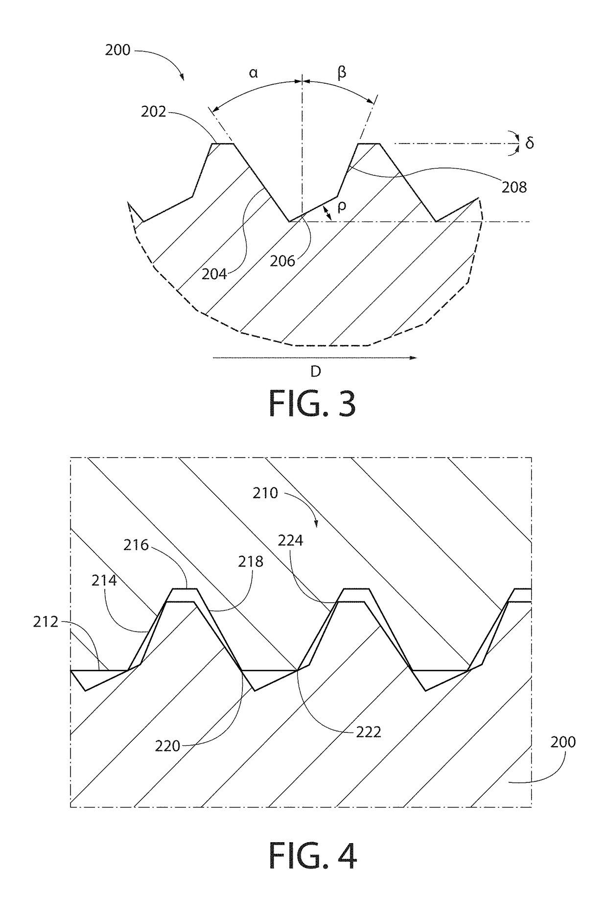
[0033]Referring now to FIGS. 3-4, a thread 200 of a threaded fastener is illustrated. The crest portion 202 oriented at a crest angle δ of approximately −5° to 5° relative to the longitudinal axis of the fastener. The crest angle δ may also be approximately 0°. The leading flank 204 is oriented at a lead angle α of approximately 25° to 45° relative to the normal axis of the fastener. The lead angle α may also range from 30° to 40°, 32° to 38°, 34° to 36°, or is approximately 35°. The root portion 206 is oriented at a root angle ρ of approximately 17° to 37° relative to the longitudinal axis of the fastener. The root angle ρ may also range from 20° to 34°, 22° to 32°, 24° to 30°, 26° to 28°, or is approximately 27°. The trailing flank 208 is oriented at trail angle β of approximately 12° to 32° relative to the normal axis. The trail angle β may also range from 14° to 30°, 16° to 28°, 18° to 26°, 20° to 24°, or is approximately 22°.

[0034]Referring to FIG. 4, the thread 200 provides th...

second embodiment

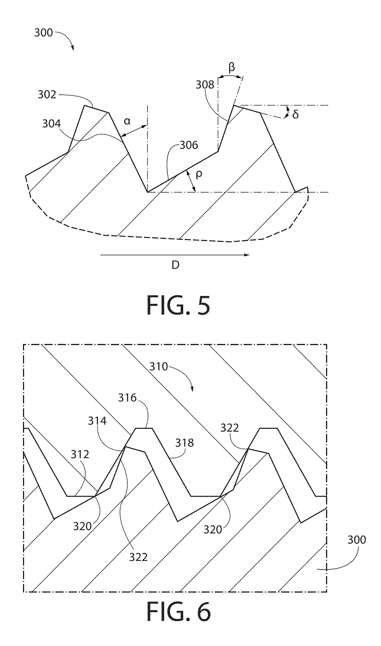
[0037]Referring now to FIGS. 5-6, a thread 300 of a threaded fastener is illustrated. The crest portion 302 oriented at a crest angle δ of approximately 5° to 25° relative to the longitudinal axis of the fastener. The crest angle δ may also range from 7° to 23°, 9° to 21°, 11° to 19°, 13° to 17°, or approximately 15°. The leading flank 304 is oriented at a lead angle α of approximately 15° to 35° relative to the normal axis of the fastener. The lead angle α may also range from 17° to 32°, 19° to 30°, 21° to 28°, 23° to 26°, or may be approximately 25°. The root portion 306 is oriented at a root angle ρ of approximately 20° to 40° relative to the longitudinal axis of the fastener. The root angle ρ may also range from 22° to 38°, 24° to 36°, 26° to 34°, 28° to 32°, or may be approximately 30°. The trailing flank 308 is oriented at trail angle β of approximately 10° to 30° relative to the normal axis. The trail angle β may also range from 12° to 28°, 14° to 26°, 16° to 24°, 18° to 22°,...

third embodiment

[0041]Referring now to FIGS. 7-8, a thread 400 of a threaded fastener is illustrated. The crest portion 402 oriented at a crest angle δ of approximately −5° to 5° relative to the longitudinal axis of the fastener. The crest angle δ may also be approximately 0°. The leading flank 404 is oriented at a lead angle α of approximately 20° to 40° relative to the normal axis of the fastener. The lead angle α may also range from 22° to 38°, 24° to 36°, 26° to 34°, 28° to 32°, or approximately 30°. The root portion of the thread 400 includes a first root portion 406 and a second root portion 407. The first root portion 406 is oriented at a first root angle ρ1 of approximately 0° relative to the longitudinal axis of the fastener. The second root portion 407 is oriented at a second root angle ρ2 of approximately 30° to 50° relative to the longitudinal axis of the fastener. The second root angle ρ2 may also range from 32° to 48°, 34° to 46°, 36° to 44°, 38° to 42°, or approximately 40°. The trai...


PUM


Abstract

Disclosed are new thread profiles that provide multi-point contact improving the vibration resistance of the threaded fastener, and thereby greatly reducing the need for fastener coatings, such as nylon patches. In various embodiments, the threaded faster may have a threaded portion configured to engage two or three points of a mating thread, and the threaded portion has a thread defined by a crest portion, a leading flank, at least one root portion, and a trailing flank, all of which may be oriented at angle relative to the normal axis.

Description

[0001]This application claims the benefit of U.S. provisional application 62 / 199,416, filed on Jul. 31, 2015.BACKGROUND AND SUMMARY[0002]The present invention relates generally to threaded fasteners of any size, and more particularly to vibration resistant threaded fasteners.[0003]Threaded fasteners such as screws are used in many applications to connect one component or part to another. Many screws are installed through a portion of one component and threaded into a second component to clamp the components together. Many component shapes and configurations have been contemplated for retaining a threaded fastener, such as a blind or through hole formed in the component for engaging the threads of the fastener. The blind or through hole may be provided in an embossment or may be provided in the component material thickness. Often the blind or through hole is threaded to mate with the threaded fastener.[0004]Many applications including automotive, electronic, and consumer products req...

Claims


Application Information

Patent Timeline
Patent Type & Authority Patents(United States)
IPC IPC(8): F16B35/04F16B39/30F16B33/02F16B25/00
CPCF16B25/0073F16B25/0084F16B39/30F16B35/04F16B33/02
Inventor PHUA, CHENG SIONGKOTHANDARAMAN, SENTHIL KUMARAN
Owner INFASTECH INTPROP PTE
Why Eureka
Try Eureka