Assembled-battery stacker and assembled battery

a technology of assembled batteries and stackers, which is applied in the manufacture of final products, cell components, cell components, etc., can solve the problems of deterioration and expansion of battery blocks, and achieve the effect of reducing raw materials, reducing the cost of raw materials, and reducing the size of assembled batteries

Active Publication Date: 2019-02-05
NIPPON STEEL CORP
View PDF32 Cites 1 Cited by
  • Summary
  • Abstract
  • Description
  • Claims
  • Application Information

AI Technical Summary

Benefits of technology

[0033]According to the above-described structure, since the end plate and the connecting member are formed from respective steel sheets, the end plate and the connecting member can be formed thinner than a case where the end plate and the connecting member are made by a die casting method with metals such as Aluminum, and an Aluminum alloy. Further, the thickness for realizing the required strength can be extremely thinner than a case where a connecting member is formed from resin. Accordingly, by the present invention, the weight saving of an assembled-battery stacker is realized, the cost of raw materials is reduced, and the downsizing of assembled-battery (space saving) is attained. Since heat conductivity of steel is higher than that of resin, it is possible to obtain an excellent heat dissipation property.
[0034]Furthermore, the productivity of the end plate and the connecting member, which are formed from respective steel sheet, can be enhanced by introducing press working. The end plate formed with a bottom wall part and a side all part can be produced by a bending process performed on a flat steel sheet of predetermined shape. Thus, the processing cost can be reduced.
[0035]In comparison with the other parts, high stress is applied to the end plate, specifically to the transient part of the bottom wall part and the side wall part in the end plate, when a battery is expanded by the deterioration of the battery. According to the present invention, the transient part is constructed by a double structure of the end plate (at least a part of the side wall part) and the connecting member. Thus, the stress concentration in the vicinity of the transient part is relaxed by the double structure. Accordingly, even a steel sheet whose proof stress is low and / or thickness is thin can be applied to both the end pale and the connecting member.

Problems solved by technology

After repetitive charge and discharge, the battery block is deteriorated and expands.

Method used


Image

  • Assembled-battery stacker and assembled battery
  • Assembled-battery stacker and assembled battery
  • Assembled-battery stacker and assembled battery

Examples


Embodiment Construction

[0044]An assembled-battery stacker 10 according to an embodiment of the present invention will be explained as follows with the help of the attached drawings.

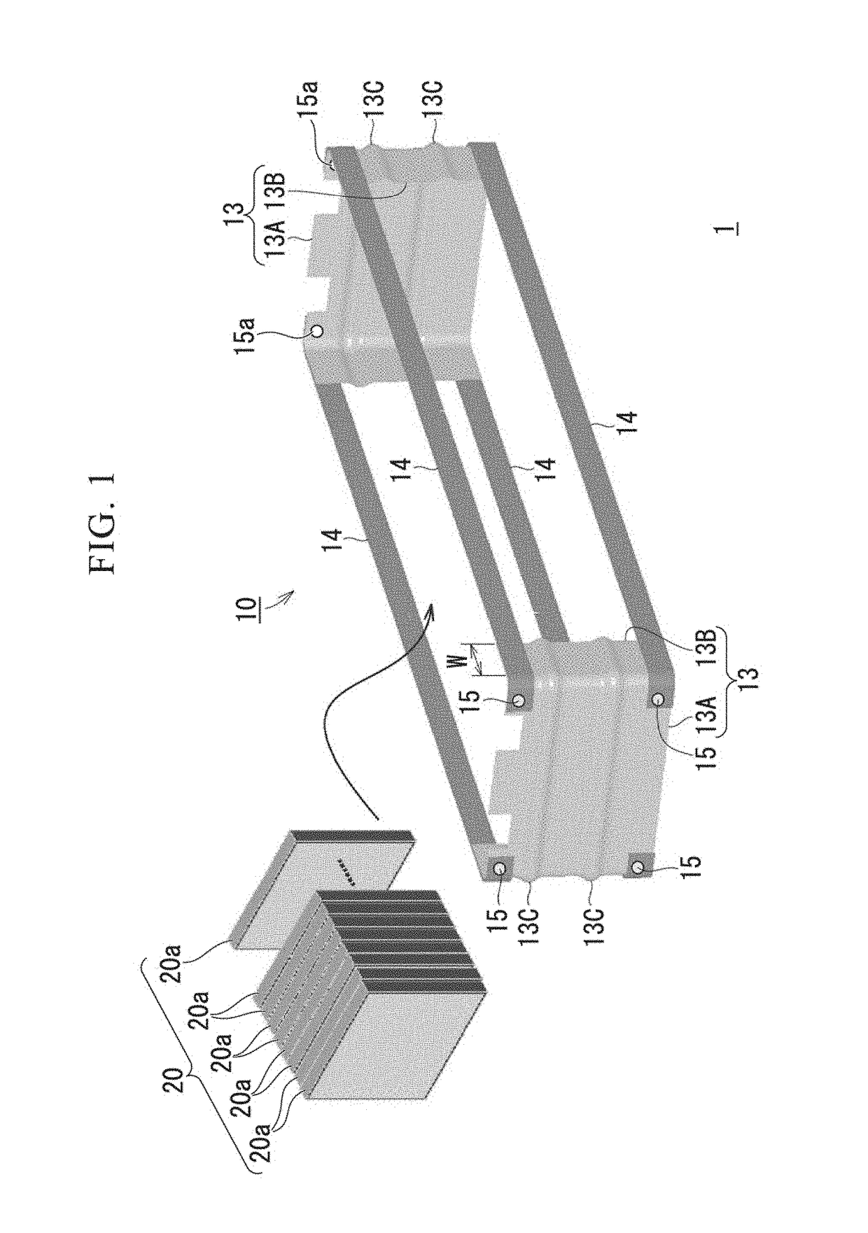
[0045]FIG. 1 is a disassembled perspective view of an assembled-battery 1 including the assembled-battery stacker 10 of the embodiment of the present invention.

[0046]The assembled-battery stacker 10 according to this embodiment is a member of an assembled-battery 1, and is configured to contain and fix a battery block 20. The battery block 20 is a component in which plate batteries 20a are stacked in the thickness direction (stacking direction). The plate battery 20a is so called a square type battery, that is, the shape is rectangular when viewed from the thickness direction of battery block 20.

[0047]The assembled-battery stacker 10 of this embodiment includes a pair of end plates 13 arranged at the both ends of the battery block 20 in the thickness direction and a connecting member 14 that mutually connects the pair of the en...


PUM

PropertyMeasurementUnit
tensile strengthaaaaaaaaaa
curvature radiusaaaaaaaaaa

Abstract

This assembled-battery stacker includes: a pair of end plates which is formed from a first steel sheet and is arranged at both ends of a battery block in the thickness direction; a connecting member which is formed from a second steel sheet and mutually connects the pair of the end plates; wherein the end plate includes: a bottom wall part that faces an end face of the battery block in the thickness direction; and a side wall part that extends from both sides of the bottom wall part to the thickness direction and covers a part of a lateral face of the battery block; and wherein the connecting member is arranged in order for the connecting member to overlap at least a part of the side wall part.

Description

TECHNICAL FIELD OF THE INVENTION[0001]This application is a national stage application of International Application No. PCT / JP2014 / 069393, filed on Jul. 23, 2014, which claims priority to Japanese Patent Application No. 2013-155097 filed on Jul. 26, 2013, each of which is incorporated herein by reference in its entirety.[0002]This invention relates to assembled-battery stacker and assembled-battery.RELATED ART[0003]In this specification, ‘battery block’ means ‘a plurality of plate batteries stacked in the thickness direction’. ‘The thickness direction of battery block’ means ‘the stacked direction of a plurality of plate batteries’. ‘Assembled-battery’ means ‘a component in which a battery block is fixed by an assembled-battery stacker’.[0004]Generally, assembled-battery stackers, for example, include a pair of end plates which is provided at both ends of the thickness direction of battery block and a connecting member which extends to the thickness direction of the battery block an...

Claims


Application Information

Patent Timeline
Patent Type & Authority Patents(United States)
IPC IPC(8): H01M2/10H01M10/04H01M10/6554H01M50/209H01M50/224H01M50/233H01M50/264
CPCH01M2/1016H01M2/1022H01M10/0481H01M2/1077H01M10/6554Y02E60/10Y02P70/50H01M50/233H01M50/224H01M50/209H01M50/264
Inventor HAMADA, KOICHI
Owner NIPPON STEEL CORP
Why Eureka
Try Eureka