Supercharge Your Innovation With Domain-Expert AI Agents!

Method for ventilating brake discs of an aircraft wheel

a technology of brake discs and aircraft wheels, which is applied in the direction of brake cooling, aircraft braking arrangements, braking systems, etc., can solve the problems of occupying a lot of space and diminishing the measurement taken by the wheel speed sensor, so as to improve the quality of the measurement and the effect of small spindl

Active Publication Date: 2019-02-12
SAFRAN LANDING SYSTEMS
View PDF13 Cites 4 Cited by
  • Summary
  • Abstract
  • Description
  • Claims
  • Application Information

AI Technical Summary

Benefits of technology

This patent describes a design where a compressor is integrated into a wheel, which means it doesn't take up space in the axle. As a result, the wheel can have a speed sensor and a rim that can be easily inspected and accessed. The compressor is small and can improve the accuracy of measurements.

Problems solved by technology

However, the ventilator arranged in this manner takes up a lot of space in the axle such that the spindle of the wheel speed sensor for measuring the speed of rotation of the wheel is elongated in order to pass through the ventilator and reach the wheel.
Thus, this diminishes the measurements taken by the wheel speed sensor.

Method used


Image

  • Method for ventilating brake discs of an aircraft wheel
  • Method for ventilating brake discs of an aircraft wheel
  • Method for ventilating brake discs of an aircraft wheel

Examples


first embodiment

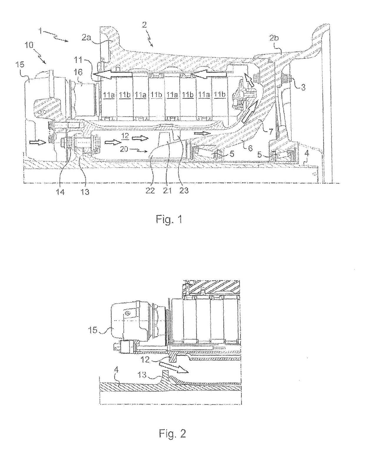
[0019]In accordance with the invention, shown in FIG. 1, there is arranged inside the torsion tube 12 an axial compressor 20 comprising rotary blades 21 mounted on a ring 22 that is secured to the rim 2 and thus rotates with the wheel, and fixed stator vanes 23 that are secured to the torsion tube. Air is drawn in by the compressor 20 via the spaces between the torsion tube 12 and the axle flange 13 (shown in FIG. 2), is delivered towards the interior of the rim and is pushed over the torsion tube 12 between the brake discs 11 and the rim 2 to exit over the braking actuators 16. Thus, the air passes along a circuit within the half-rim 2a, on either side of the torsion tube 12, as indicated by the arrows in the figure.

[0020]It will be noted that the web 7 of the half-rim 2a which extends so as to connect the hub 6 to the rest of the rim is closed and comprises no aeration openings that would allow the air flows to escape through the rim to the outside. This absence of alveoli simplif...

second embodiment

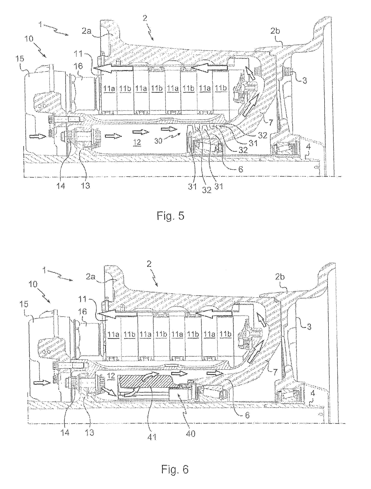
[0024]According to the invention, shown in FIG. 5, the axial compressor 30 is still installed inside the torsion tube 12, but in this case it extends more precisely between the torsion tube 12 and the hub 6 of the rim 2. In this case, the turbine 30 comprises three successive stages, each comprising rotating blades 31 followed by fixed stator vanes 32. The operation of the axial compressor 30 is identical to that of the axial compressor 20.

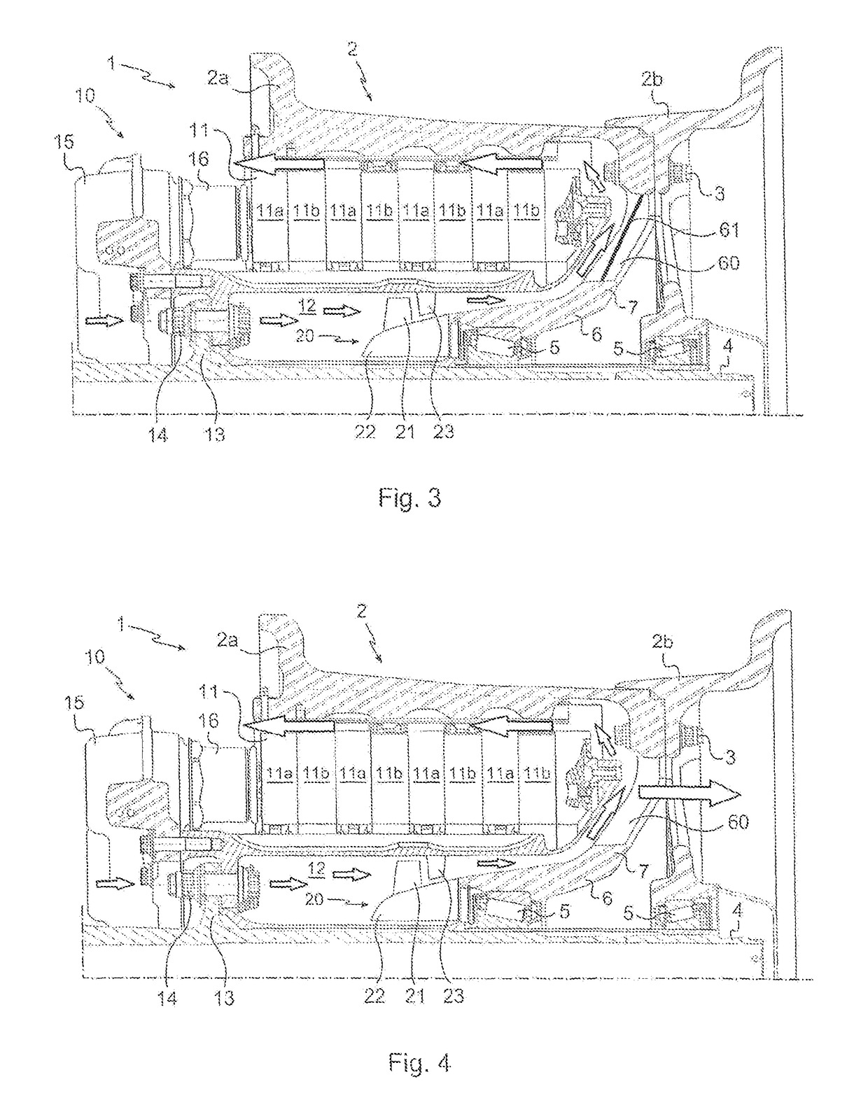
[0025]As was the case for the variants of the first embodiment, the web 7 of the half-rim 2a may, as a variant, comprise openings that are obstructed or not.

third embodiment

[0026] illustrated in FIGS. 6 and 7, the wheel is now equipped with a centrifugal (or radial) compressor 40 which still extends inside the torsion tube 12. In this case, the compressor 40 is a compressor comprising a bladed wheel 41 (here, only one blade is provided with a reference) that rotates as one with the wheel. The bladed wheel draws in air over all 360 degrees of the interior diameter of the bladed wheel 41. The compressed air is then ejected by the compressor 40 over all 360 degrees of the exterior diameter of the compressor, and thus in part towards the torsion tube 12, wherein the air then escapes by passing over the torsion tube 12 between the rim and the brake discs, as before.

[0027]As was the case for the variants of the first embodiment, the web 7 of the half-rim 2a may, as a variant, comprise openings that are obstructed or not.


PUM


Abstract

A method for ventilating discs (11) of a brake (10) fitted to an aircraft wheel (1) having a rim (2) mounted so as to rotate on an axle (4) of a landing gear of the aircraft. The brake discs are threaded onto a torsion tube (12) of the brake which extends around the axle. The method comprises the step of integrating a compressor (20; 30; 40) into a space extending inside the torsion tube in order to draw in air beneath the torsion tube and to return the air thus drawn in by the compressor over the torsion tube towards the brake discs.

Description

[0001]The invention relates to a method for ventilating brake discs of an aircraft wheel.TECHNOLOGICAL BACKGROUND OF THE INVENTION[0002]Already known are aircraft whose wheels equipped with a brake are provided with a ventilator that can be controlled so as to cool the brake discs in order to rapidly lower their temperature and thus avoid any delay to the departure of the aircraft for a new cycle. In general, the body of the ventilator is engaged inside the axle bearing the wheel, and its turbine draws in the air through openings in the rim of the wheel. However, the ventilator arranged in this manner takes up a lot of space in the axle such that the spindle of the wheel speed sensor for measuring the speed of rotation of the wheel is elongated in order to pass through the ventilator and reach the wheel. Thus, this diminishes the measurements taken by the wheel speed sensor.[0003]Also known, in particular in the automotive field, are turbines secured to the rim of the wheel in order...

Claims


Application Information

Patent Timeline
Patent Type & Authority Patents(United States)
IPC IPC(8): F16D65/847B64C25/42B60T5/00F16D55/36
CPCF16D65/847B64C25/42B60T5/00F16D55/36B60T17/02
Inventor GONZALEZ, VINCENTGAPIN, ARNAUD
Owner SAFRAN LANDING SYSTEMS
Features
  • R&D
  • Intellectual Property
  • Life Sciences
  • Materials
  • Tech Scout
  • Unparalleled Data Quality
  • Higher Quality Content
  • 60% Fewer Hallucinations
Learn More