Integrated emergency wash and shower system

a shower system and integrated technology, applied in mechanical equipment, valves, physical therapy, etc., can solve the problems of affecting the use of the emergency wash system, etc., to achieve convenient maintenance, low cost, and easy installation

Active Publication Date: 2019-02-26
MAGARL
View PDF115 Cites 3 Cited by
  • Summary
  • Abstract
  • Description
  • Claims
  • Application Information

AI Technical Summary

Benefits of technology

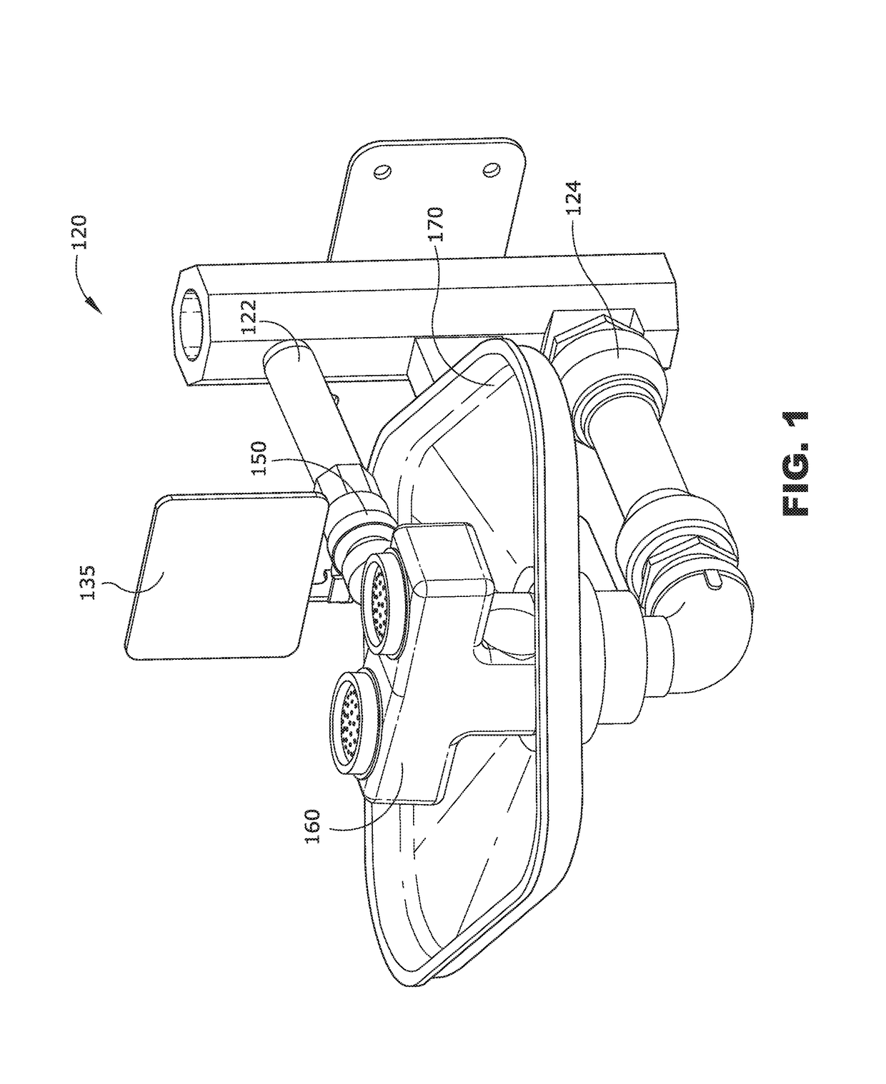
[0010]In some embodiments, there is a thermostatically controlled mixing valve that is adapted and configured to provide a sufficient flow of tepid water to more than one emergency fixture. Still further, some of these valves are configured such that they provide structural support to the emergency fixtures. Some embodiments of the present invention include a body for a mixing valve in which the water inlet and water mixing functions are placed in one portion of the valve, and the structural support functions are performed with a different portion of the valve body. In so doing, these two functions of precision mixing and structural support are spatially separated. Preferably, the structural support functions are provided in a portion of the body that is entirely on one side of the body. Therefore, any loads going in or out of this structural support section will not create stresses or distortion in the portion of the body that maintains the precision metering section. Structural loads can be maintained by such a thermostatically controlled valve, with no interactions of these loads on the fluid mixing operations performed by the valve.
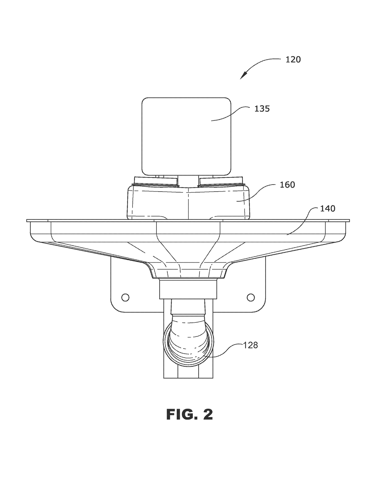
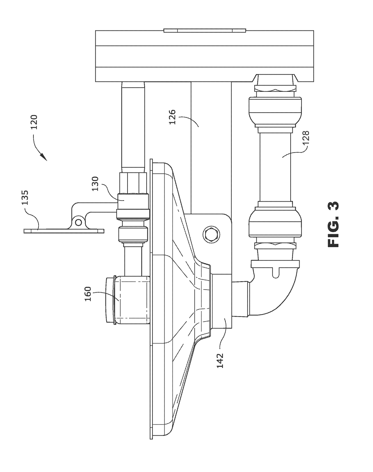
[0011]Yet other embodiments of the present invention pertain to integrated washing systems in which a minimum number of components provide all the required safety washing functions within U.S. government safety guidelines, but further permit an overall system package that is space efficient, easy to install, easy to maintain, and low cost. As one example, in some embodiments the washing systems are provided with tempered, mixed fluid provided in straight-forward flow paths that double as structural support. In those systems in which there is a single thermostatically controlled valve, this valve can be located between the eyewash and shower in straight line fashion, or located at either of the two washing stations, supporting one of them in cantilevered fashion. Still further, various embodiments of the present invention include integrated thermostatically controlled valves in which the metering section is placed closest to the wall or other surface of the laboratory or production facility, with the outlet chamber of the mixing valve being spaced away from that same surface. Preferably, this spacing is sufficient to accommodate existing piping in the facility. For example, the inlet flowpath may be located directly against the surface, and likewise there may be other fluid flowpaths, electrical conduits, or the like located against that same surface. By spacing out the outlet chamber of the mixing valve away from this surface, it is easy for the installer to locate the emergency wash fixtures with little or no interference with the pre-existing surroundings.

Problems solved by technology

Space on the manufacturing floor can be especially costly.
Yet another factor that complicates the problems thus discussed is the desire to use less water in any new water-handling device.
If an emergency washing system is not comfortable, then it is less likely to be used, which defeats the purpose of the emergency wash system.
It has been observed that some eye washing systems produce output sprays that are too strong or flow too high to be comfortably used.
It has been found that an emergency washing system adapted and configured to provide a low flow rate of tepid water can be susceptible to variations as to overall low delivery pressures, as well as relative differences in pressure between the hot and cold inlets.

Method used


Image

  • Integrated emergency wash and shower system
  • Integrated emergency wash and shower system
  • Integrated emergency wash and shower system

Examples


Embodiment Construction

[0116]For the purposes of promoting an understanding of the principles of the invention, reference will now be made to the embodiments illustrated in the drawings and specific language will be used to describe the same. It will nevertheless be understood that no limitation of the scope of the invention is thereby intended, such alterations and further modifications in the illustrated device, and such further applications of the principles of the invention as illustrated therein being contemplated as would normally occur to one skilled in the art to which the invention relates. At least one embodiment of the present invention will be described and shown, and this application may show and / or describe other embodiments of the present invention.

[0117]It is understood that any reference to “the invention” is a reference to an embodiment of a family of inventions, with no single embodiment including an apparatus, process, or composition that should be included in all embodiments, unless o...


PUM


Abstract

Apparatus and methods for integrated emergency wash systems. Various embodiments include thermostatically controlled mixing valves arranged so as to permit load carrying by the body of the valve. Further, the integrated wash systems are especially suited for use in laboratories and manufacturing settings in which available space is at a premium.

Description

CROSS REFERENCE TO RELATED APPLICATION[0001]This application claims the benefit of priority to U.S. Provisional Patent Application Ser. No. 62 / 191,358, filed Jul. 11, 2015, titled INTEGRATED EMERGENCY WASH AND SHOWER SYSTEM, incorporated herein by reference.FIELD OF THE INVENTION[0002]Various embodiments of the present invention pertain to methods and apparatus for emergency washing, and in particular to eyewash, facewash, or bodywash apparatus.BACKGROUND OF THE INVENTION[0003]Emergency eyewashes and showers are used in a variety of industrial, educational, and governmental settings in which dangerous chemicals are present. Should a user's eyes become contaminated (or the user's body become contaminated) a nearby, easy to use, and safe emergency washing system can provide quick and thorough flushing of the contamination.[0004]Often, these emergency wash systems are located in laboratories or manufacturing areas in which space is at a premium. Therefore, it becomes important to effic...

Claims


Application Information

Patent Timeline
Patent Type & Authority Patents(United States)
IPC IPC(8): A47K3/28A61H35/02F16K31/00F16K11/00
CPCA47K3/286F16K31/002F16K19/006A61H35/02
Inventor EVELEIGH, ROBERT B.BAKER, THOMAS R.WEST, CAMERON
Owner MAGARL
Why Eureka
Try Eureka