Composite rail tie apparatus and method

a technology of rail tie and composite material, applied in the direction of threaded fasteners, rod connections, ways, etc., can solve the problems of spikes that have secured plates to the ties, may eventually begin to loosen, and work loose, so as to reduce cost and density or total weight, resist chafing, and resist deflection

Active Publication Date: 2019-02-26
HAWKINS MICHAEL A +1
View PDF13 Cites 1 Cited by
  • Summary
  • Abstract
  • Description
  • Claims
  • Application Information

AI Technical Summary

Benefits of technology

[0015]A fill material may be selected from concrete, lightweight concrete, expanded polymer, expanded elastomer (elastomeric polymer), or the like. Any fill may, in turn, include an “inner fill” or “bulking agent” such as air, glass beads (hollow spheres), polymer bubbles or spheres, to bulk it up while reducing cost and density or total weight. These may include also sawdust, recycled wood, recycled wooden rail ties, or the like
[0016]Meanwhile, the axial cross-section of a tie may be designed to provide the proper mechanical properties to support a railroad rail passing over a tie. These include supporting the load, resisting chafing, securing the rail to the tie, resisting deflection, resisting buckling, retaining a spike or other fastener, and resisting weather, wear, and the other environmental exposure expected for a rail tie.

Problems solved by technology

Over time, the spikes that have secured plates to the ties, may eventually begin to loosen.
As wood weathers, splits, shrinks, and the like, the spikes may loosen.
Accordingly, the base plate underneath each rail, on top of a tie, as well as the securement plates that attach over the top of the base of the rail, may work loose and fail to provide adequate securement.
Meanwhile, recycling of the rubber from tires has become a major storage and remanufacturing issue.

Method used


Image

  • Composite rail tie apparatus and method
  • Composite rail tie apparatus and method
  • Composite rail tie apparatus and method

Examples


Embodiment Construction

[0063]It will be readily understood that the components of the present invention, as generally described and illustrated in the drawings herein, could be arranged and designed in a wide variety of different configurations. Thus, the following more detailed description of the embodiments of the system and method of the present invention, as represented in the drawings, is not intended to limit the scope of the invention, as claimed, but is merely representative of various embodiments of the invention. The illustrated embodiments of the invention will be best understood by reference to the drawings, wherein like parts are designated by like numerals throughout.

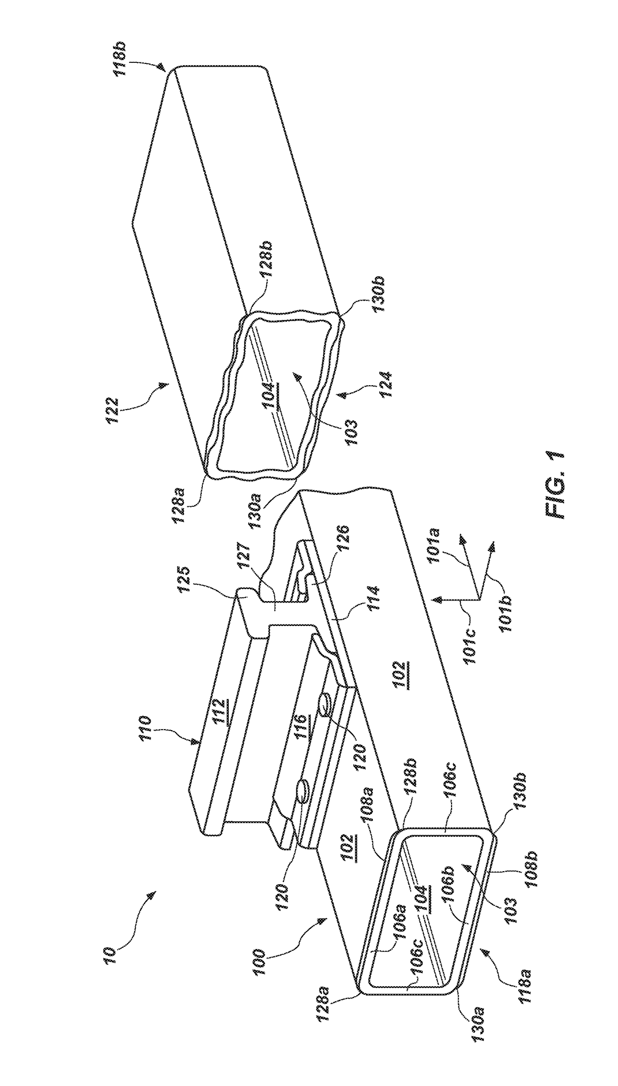
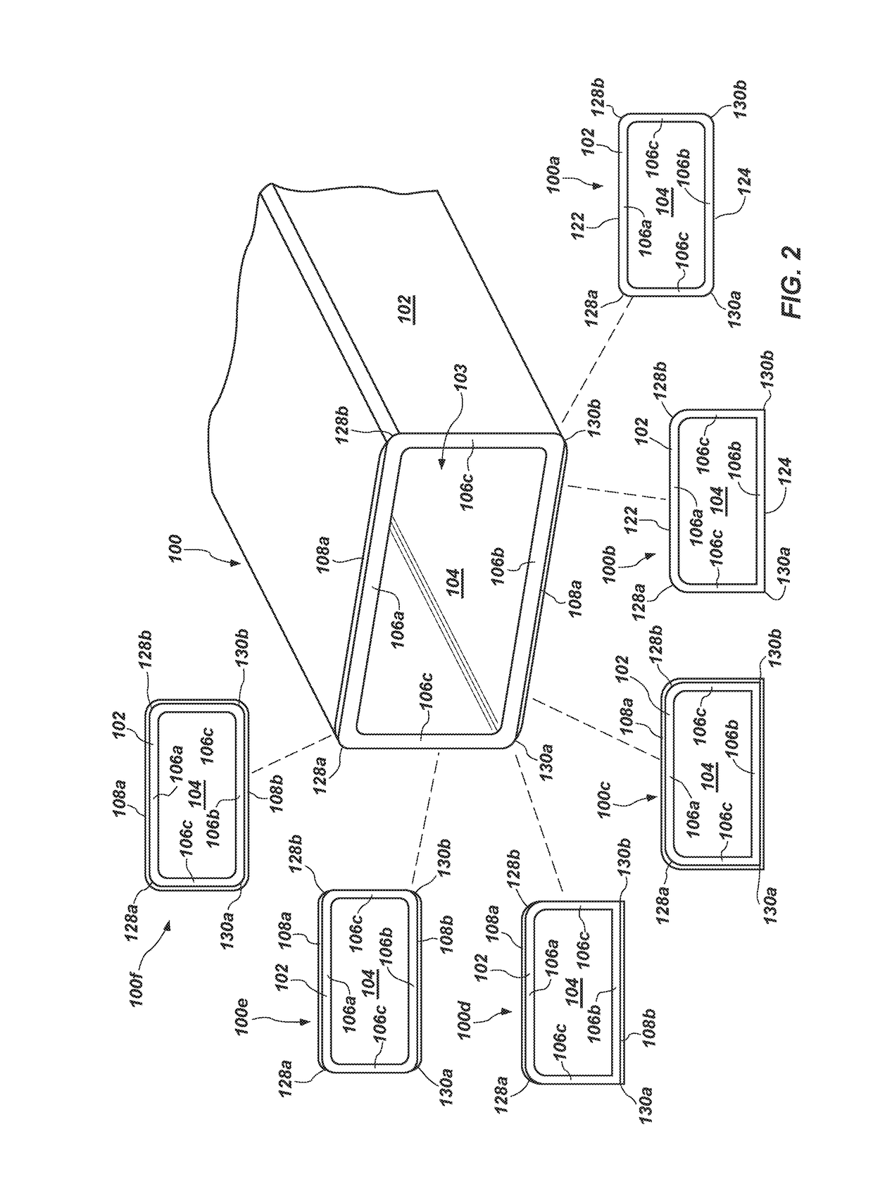
[0064]Referring to FIG. 1, a system 10 in accordance with the invention may implement a composite construction for a rail tie 100. In the illustrated embodiment, a tie 100 may be of a conventional size in order to meet replacement needs (retro fit) in systems already using conventional ties. Conventional ties are typically cut f...


PUM

PropertyMeasurementUnit
lengthaaaaaaaaaa
axial lengthaaaaaaaaaa

Abstract

A railroad crosstie (tie) may be fabricated from a composite material including a fiber reinforced polymer shell manufactured by pultrusion or other process, and filled by a suitable material, typically selected from expanded elastomeric polymer (such as polyurethane resin or other polymer), concrete, lightweight concrete formed by conventional aggregate, sand, cement, water, and an ultra light filler such as natural materials, sawdust, beads of expanded polymer such as expanded polystyrene, microspheres of glass or plastic, a recycled wooden tie in conjunction with any of the above, or the like. Fasteners may be driven such as spikes, threaded, such as screws, lag screws, spreading screws, rivets, or the like into apertures, pilot holes, or directly into fill absent apertures therein.

Description

RELATED APPLICATIONS[0001]This application claims the benefit of: U.S. Provisional Patent Application Ser. No. 62 / 106,540, filed Jan. 22, 2015; U.S. Provisional Patent Application Ser. No. 62 / 197,412, filed Jul. 27, 2015; and U.S. Provisional Patent Application Ser. No. 62 / 237,941, filed Oct. 6, 2015; all of which are incorporated herein by reference in their entirety.BACKGROUND[0002]1. Field of the Invention[0003]This invention relates to railroad crossties and, more particularly, to novel systems and methods for construction thereof from composite structural materials.[0004]2. Background Art[0005]Railroad crossties, sometimes called rail ties or simply ties, have traditionally been constructed of wood. Wood provides a structural platform sitting on top of road ballast, rock of specified size distribution. The crosstie provides sufficient “flotation” (load pressure distribution) to support the substantial weight of the axles of a railroad train passing over the top thereof. Each ra...

Claims


Application Information

Patent Timeline
Patent Type & Authority Patents(United States)
IPC IPC(8): B29C70/52B29C70/74F16B7/00E01B3/46B29C70/54B29L31/06B29L31/10
CPCB29C70/52B29C70/745E01B3/46F16B7/00B29L2031/10B29C70/545B29L2031/06F16B15/06F16B37/005
Inventor HAWKINS, MICHAEL A.HAWKINS, MICHAEL L.
Owner HAWKINS MICHAEL A
Why Eureka
Try Eureka