Apparatus for atomic clock, its operating method and its manufacturing method

a technology of atomic clock and operating method, applied in the field of electrostatic resonance detection, can solve the problems of not optimizing the alignment affecting the device performance, and the practical manufacturing of the device described in this document is also not optimized, so as to improve the frequency stability and time-keeping properties of the atomic clock, improve the uniformity of the applied magnetic field, and reduce the linewidth of the output signal

Inactive Publication Date: 2019-02-26
MEMSCAP
View PDF7 Cites 0 Cited by
  • Summary
  • Abstract
  • Description
  • Claims
  • Application Information

AI Technical Summary

Benefits of technology

[0020]Thus, the disclosed embodiments aim at providing a solution that improves the uniformity of the applied magnetic field over a large spatial range and notably over a medium capable of undergoing energetic transitions between at least two energy levels, to thereby reducing the linewidth of the output signal and improving frequency stability and time-keeping properties of the atomic clock.
[0072]In practice, the operating method may also comprise, stabilizing the temperature of the volume in which the medium is located at a substantially constant temperature.

Problems solved by technology

However, the alignment device described in this document is not optimal since it creates spatial variations of the value and of the direction of the magnetic field B0 over the spatial range of the solid layer, due notably to the so-called “corner effects” of the magnetic field generated by the alignment device.
Moreover, in this document U.S. Pat. No. 7,142,066, the sensitivity of the device to external fields (like any electro-magnetic field present in a mobile handset), which can also strongly affect the device performance, is not addressed.
Practical manufacturing of the device described in this document is also not optimized.
The ability to deposit magnetic material on top of a semiconductor wafers (or die) is limited by the thermal budget of the underlying electronics and materials.
However, in order to generate the required biasing field B0, some current needs to flow constantly in the micro-coils during the device operation which makes this solution incompatible with most recent mobile handsets power consumption requirements.
Such dimensions are completely incompatible with miniaturization and costs requirements, notably in the industry of mobile handsets and Internet of Things (IOT).
Another drawback of the solution described in this document is the complexity of operating the device and the number of elements which need to be combined to operate.
Such operation typically requires unnecessary complexity in the electronics circuitry.

Method used


Image

  • Apparatus for atomic clock, its operating method and its manufacturing method
  • Apparatus for atomic clock, its operating method and its manufacturing method
  • Apparatus for atomic clock, its operating method and its manufacturing method

Examples


Embodiment Construction

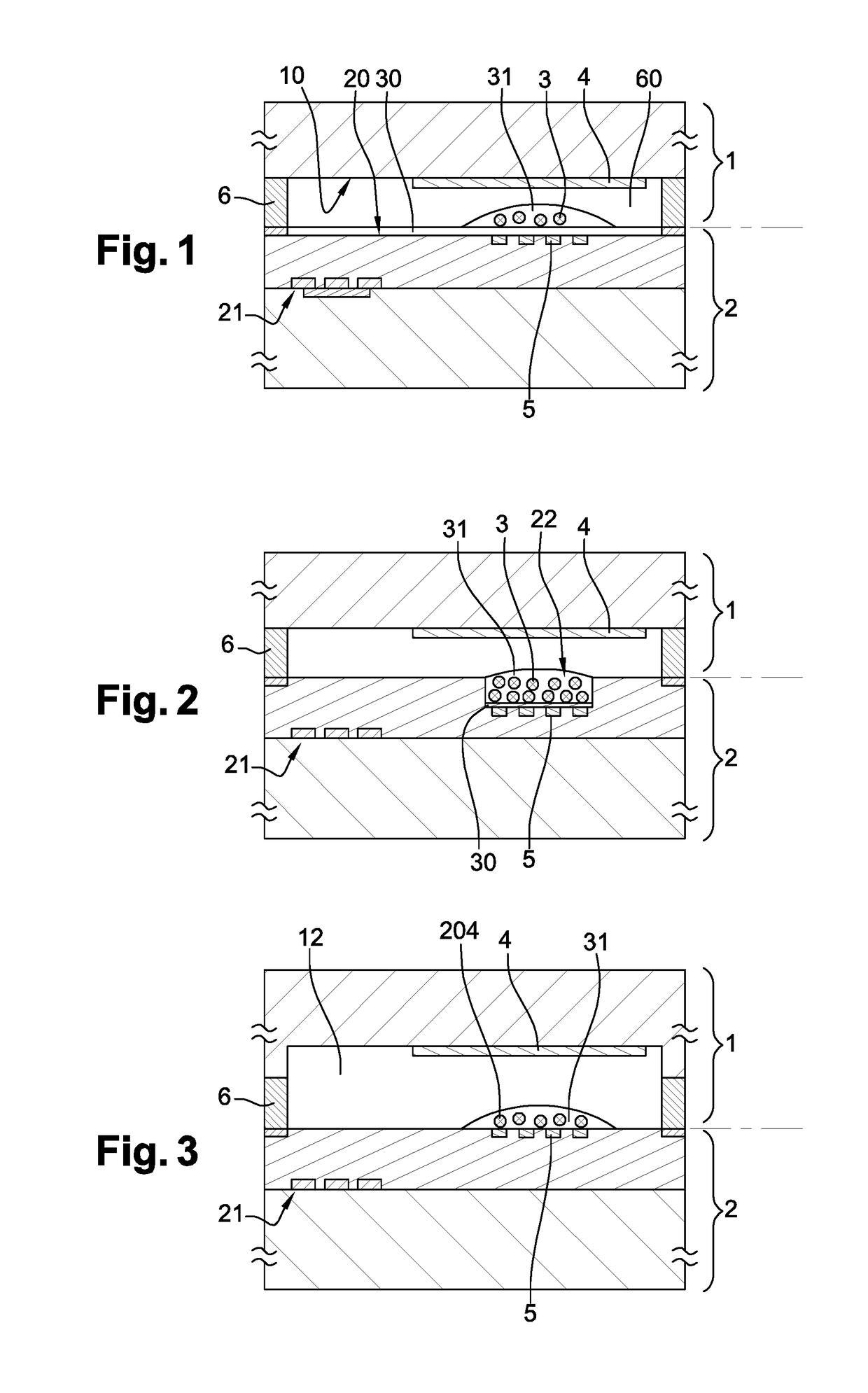
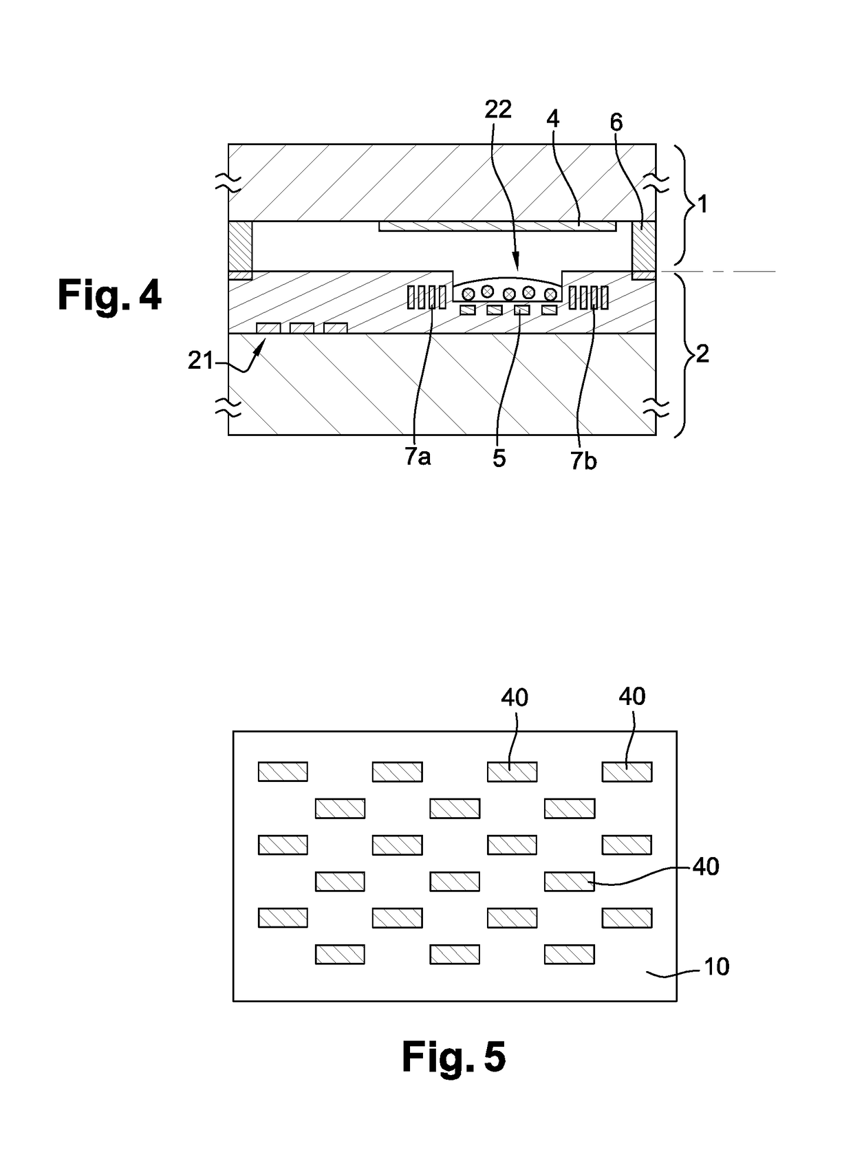
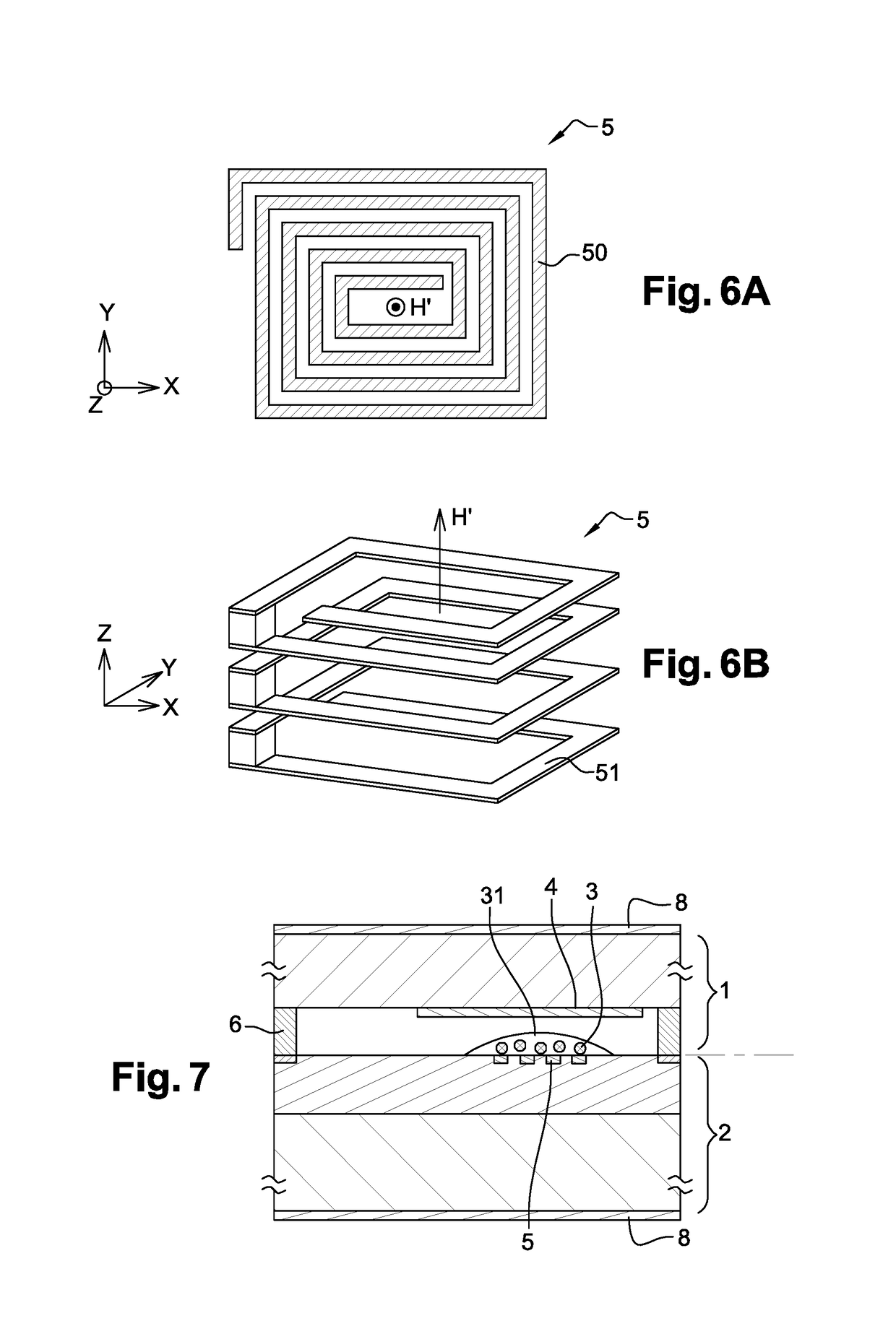
[0089]The apparatus for atomic clock according to a particular embodiment comprises notably:[0090]two distinctive substrates 1, 2;[0091]a medium 3 capable of undergoing energetic transitions between at least two energy levels;[0092]a magnetic device 4, such as a structure of permanent magnet, to produce a predetermined static magnetic field B;[0093]an excitation device 5, such as a structure of spiral micro-coils, to generate an excitation magnetic field H orthogonal to the static magnetic field B and to detect the occurrence of spin resonance of the medium;[0094]a frequency generator 54 generating a tunable frequency to be applied to the excitation device;[0095]a detection device 52 monitoring the excitation device in order to detect the occurrence of a spin resonance of the medium;[0096]a frequency-lock device 53 for locking the generated tunable frequency to the frequency at which the spin resonance has occurred.

[0097]According to particular embodiments illustrated in FIGS. 1 to ...


PUM

PropertyMeasurementUnit
temperatureaaaaaaaaaa
magnetic field intensityaaaaaaaaaa

Abstract

An apparatus for an atomic clock includes first and second distinctive substrates, each having at least a planar surface substantially parallel therebetween. The apparatus also includes a medium having particles capable of undergoing energetic transition between at least two energy levels, said medium being located in the space defined between the planar surfaces. It further includes a magnetic device arranged to the first substrate and generating at least in the volume of the medium a predetermined static magnetic field B the direction of which is substantially parallel or perpendicular to the planar surfaces and an excitation device arranged to the second substrate and generating an excitation magnetic field H at, at least an excitation frequency, the direction of said excitation magnetic field H in the volume of the medium being substantially orthogonal to said direction of the static magnetic field B.

Description

CROSS-REFERENCE TO RELATED APPLICATIONS[0001]This application claims the benefit of priority under 35 U.S.C. § 119 of prior-filed European Patent Application No. 15175309.2, filed Jul. 3, 2015, the entire content of which is hereby incorporated herein by reference, in its entirety and for all purposes.TECHNOLOGICAL FIELD[0002]The present disclosure is in the general field of electron spin resonance detection. More precisely, it relates to spin resonance detection device for the realization of miniature atomic clocks, its operating method and its manufacturing method.BACKGROUND[0003]Spin resonance spectroscopy (ESR) or Electron paramagnetic resonance (EPR) is a widely used technique for studying and characterizing materials with unpaired electrons. The technique depends on the fact that certain atomic systems have a permanent magnetic moment. The energy levels of the magnetic system are influenced by the surrounding atoms and by external magnetic fields.[0004]Every electron has a mag...

Claims


Application Information

Patent Timeline
Patent Type & Authority Patents(United States)
IPC IPC(8): H03L7/26G04F5/14G01N24/10G01R33/30G01R33/60G01R33/383
CPCG04F5/14G01N24/10G01R33/60H03L7/26G01R33/302G01R33/383
Inventor BERTSCH, NICOLAS
Owner MEMSCAP
Why Eureka
Try Eureka