Terminal fitting and connector

a technology of terminal fittings and connectors, applied in the direction of connecting, coupling contact members, electrical equipment, etc., can solve the problems of high friction coefficient of terminal fittings, terminal fittings exposed to hot and humid environments, etc., to reduce the friction coefficient of outermost surfaces, reduce the insertion force of terminals, and suppress the effect of surface oxidation of plating films

Active Publication Date: 2019-02-26
AUTONETWORKS TECH LTD +2
View PDF20 Cites 30 Cited by
  • Summary
  • Abstract
  • Description
  • Claims
  • Application Information

AI Technical Summary

Benefits of technology

[0007]The present design was made in view of the above-described circumstances, and it is an object thereof to provide a terminal fitting that needs a less terminal insertion force, and can suppress surface oxidation of a plating film even if the terminal fitting is exposed to a hot and humid environment, and a connector that uses the terminal fitting.
[0014]In the terminal fitting, the outermost layer of the plating film may include: a Sn parent phase; and an intermetallic compound that is dispersed in the Sn parent phase, and is made of (Ni0.4Pd0.6)Sn4. The intermetallic compound is harder than Sn. Therefore, since the outermost layer contains the intermetallic compound, adhesion or scratching of the parent phase of the plating film is unlikely to occur, and the friction coefficient of the outermost surface can be reduced relative to a conventional Sn plating film. Accordingly, the terminal fitting can reduce the terminal insertion force.
[0015]Furthermore, even if the intermetallic compound is exposed to a hot and humid environment, an oxidized film is unlikely to grow on the intermetallic compound any more than before it is exposed to the hot and humid environment. Accordingly, the terminal fitting can suppress surface oxidation of the plating film even if it is exposed to a hot and humid environment.
[0016]The connector can include the above-described terminal fitting, and thus can reduce the insertion force needed when it is connected to a counterpart connector. Also, the connector is unlikely to corrode even if it is exposed to a hot and humid environment, and is superior in the resistance to environment.

Problems solved by technology

However, the terminal fitting disclosed in Patent Document 1 has a high friction coefficient because it has the relatively soft Sn plating layer at its surface, and needs a large terminal insertion force when being connected to a counterpart terminal fitting.
Meanwhile, there may be cases where a terminal fitting is exposed to a hot and humid environment.
Therefore, even if a connector to which such a terminal fitting is applied can reduce the insertion force needed when being connected to a counterpart connector, the connector is likely to corrode and has poor resistance to environment.
Furthermore, even if the intermetallic compound is exposed to a hot and humid environment, an oxidized film is unlikely to grow on the intermetallic compound any more than before it is exposed to the hot and humid environment.

Method used


Image

  • Terminal fitting and connector
  • Terminal fitting and connector
  • Terminal fitting and connector

Examples


embodiment 1

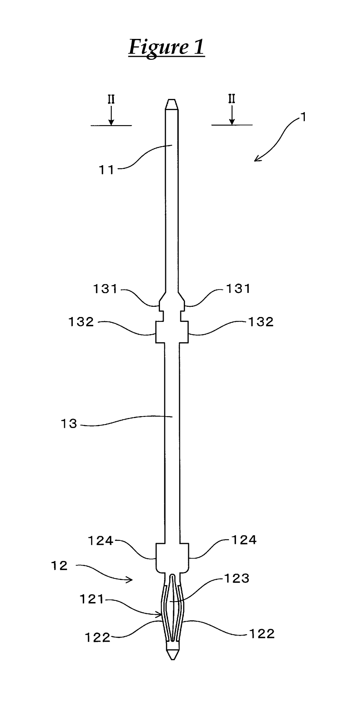
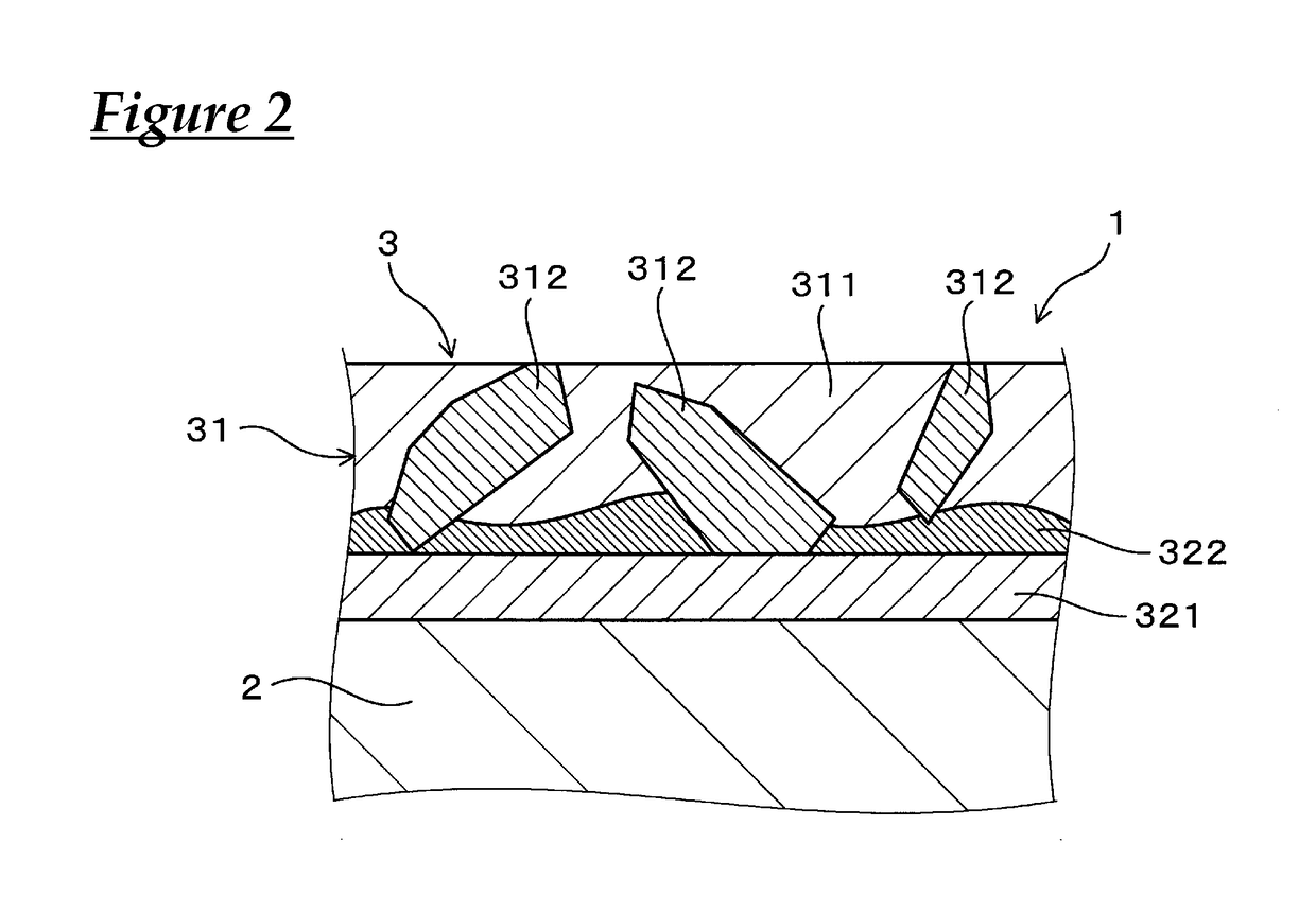
[0052]The terminal fitting according to Embodiment 1 will be described with reference to FIGS. 1 to 5. As shown in FIGS. 1 to 5, a terminal fitting 1 of the present embodiment includes a metal base material 2, and a plating film 3 that covers a surface of the metal base material 2. The plating film 3 has an outermost layer 31 that is exposed at the outermost surface. The outermost layer 31 includes an intermetallic compound 312.

[0053]The plating film 3 includes a Ni foundation layer 321 that is formed on the surface of the metal base material 2, and the outermost layer 31 that is formed above the Ni foundation layer 321, and is exposed at the outermost surface of the plating film 3. The outermost layer 31 includes a Sn parent phase 311, and the intermetallic compound 312 that is dispersed in the Sn parent phase 311.

[0054]In the present embodiment, the metal base material 2 is specifically a Cu alloy. Furthermore, the intermetallic compound 312 is made of (Ni0.4Pd0.6)Sn4. The particl...

experimental examples

[0067]Hereinafter, more specific description will be given with reference to experimental examples.

[0068]Sample 1 was produced by sequentially forming a Ni plating film (thickness: 1 μm), a Pd plating film (thickness: 0.02 μm), and a Sn plating film (thickness: 1.5 μm) on a surface of a Cu alloy plate material, and then subjecting the resultant to reflow processing at 350° C.

[0069]Sample 2 was produced in the same manner as in Sample 1 but using a Pd plating film (thickness: 0.025 μm), and a Sn plating film (thickness: 1.25 μm) instead. Furthermore, Sample 3 was produced in the same manner as in Sample 1 but using a Pd plating film (thickness: 0.03 μm) and a Sn plating film (thickness: 1.0 μm) instead. Note that for comparison, Sample 1C was produced by sequentially forming a Ni plating film (thickness: 1 μm), and a Sn plating film (thickness: 1 μm) on a surface of a Cu alloy plate material, and then subjecting the resultant to reflow processing at 350° C.

[0070]Then, cross-sections ...


PUM

PropertyMeasurementUnit
particle diameteraaaaaaaaaa
friction coefficientaaaaaaaaaa
particle diametersaaaaaaaaaa

Abstract

A terminal fitting that can reduce the terminal insertion force and can suppress surface oxidation of a plating film, even if the terminal fitting is exposed to a hot and humid environment, and a connector that uses the terminal fitting. The terminal fitting includes a metal base material, and the plating film. The plating film includes a Ni foundation layer, an outermost layer exposed at the outermost surface, and a Ni3Sn4 layer formed between the Ni foundation layer and the outermost layer. The outermost layer includes a Sn parent phase, and intermetallic compound that is dispersed in the Sn parent phase, and is made of (Ni0.4Pd0.6)Sn4. The intermetallic compound protrudes from the lower side of the outermost layer to the Ni3Sn4 layer side, and is partially buried in the Ni3Sn4 layer. A connector includes the terminal fitting, and a housing that holds the terminal fitting.

Description

CROSS REFERENCE TO RELATED APPLICATIONS[0001]This application claims the priority of Japanese patent application JP2015-218753 filed on Nov. 6, 2015, the entire contents of which are incorporated herein.TECHNICAL FIELD[0002]The present invention relates to a terminal fitting and a connector.BACKGROUND ART[0003]As terminal fittings for use in connection of an electric circuit, terminal fittings are known that include a metal base material made of a Cu alloy, and a Sn plating film that covers a surface of the metal base material. Terminal fittings include fitting-type terminals that are crimped to ends of electric wires, substrate terminals that are attached to circuit boards, and the like. These terminal fittings may be used alone, or may be used while being attached to connectors.[0004]As a terminal material used for terminal fittings, a terminal material is often used that is obtained by stacking an Ni plating layer, a Cu plating layer, and a Sn plating layer sequentially on a surf...

Claims


Application Information

Patent Timeline
Patent Type & Authority Patents(United States)
IPC IPC(8): H01R13/03C25D7/00C25D5/50H01R43/16C25D5/12H01R12/58
CPCC25D5/12C25D5/505H01R13/03H01R12/585C25D5/605
Inventor WATANABE, HAJIMESAKA, YOSHIFUMI
Owner AUTONETWORKS TECH LTD
Why Eureka
Try Eureka