Display device for vehicle

a technology for vehicle information and display device, which is applied in the direction of projection device, television system, picture reproducer, etc., can solve the problems of vehicle information that is necessary for a user that does not necessarily match with vehicle information, and the degree of effectiveness of vehicle information may be reduced, so as to improve the effectiveness and secure the notification of vehicle information

Inactive Publication Date: 2019-03-05
DENSO CORP
View PDF10 Cites 0 Cited by
  • Summary
  • Abstract
  • Description
  • Claims
  • Application Information

AI Technical Summary

Benefits of technology

[0007]However, vehicle information necessary for a user does not necessarily match with vehicle information at which the user gazes. For example, when a particular virtual image display in the display screen area is configured to link with a real image display of the meter unit in response to a switch operation or the like capable of transmitting a more accurate intention of the user than gazing by the user, a mismatch may be produced between necessary information and gaze information. When a mismatch between necessary information and gaze information is present, the degree of effectiveness of the vehicle information may lower.
[0008]When a virtual image in the display screen area is displayed in linkage with a real image display of the meter unit, the user does not easily notice the virtual image at the time of linkage. In this case, the user does not pay attention to necessary information. Accordingly, the degree of secure notification of vehicle information achievable through the linkage may lower.
[0009]It is an object of the present disclosure to provide a display device for a vehicle to enhance effectiveness and secure notification of vehicle information.
[0015]During the linking period, a particular virtual image of the second information displayed in the second display portion above the first display portion is linked with a real image of the first information displayed in the first display portion. At this time, the light emission area of the light emission portion disposed on the side of the first display portion changes in the guiding direction from the first display portion to the second display portion. In this case, a user inside the vehicle directs a gaze to the particular second information requiring notification in association with the first information, because the eyes of the user are guided toward the second information. The linkage of display realizes matching between necessary information and gaze information, and improves effectiveness and secure notification of vehicle information.

Problems solved by technology

However, vehicle information necessary for a user does not necessarily match with vehicle information at which the user gazes.
For example, when a particular virtual image display in the display screen area is configured to link with a real image display of the meter unit in response to a switch operation or the like capable of transmitting a more accurate intention of the user than gazing by the user, a mismatch may be produced between necessary information and gaze information.
When a mismatch between necessary information and gaze information is present, the degree of effectiveness of the vehicle information may lower.
When a virtual image in the display screen area is displayed in linkage with a real image display of the meter unit, the user does not easily notice the virtual image at the time of linkage.

Method used


Image

  • Display device for vehicle
  • Display device for vehicle
  • Display device for vehicle

Examples


first embodiment

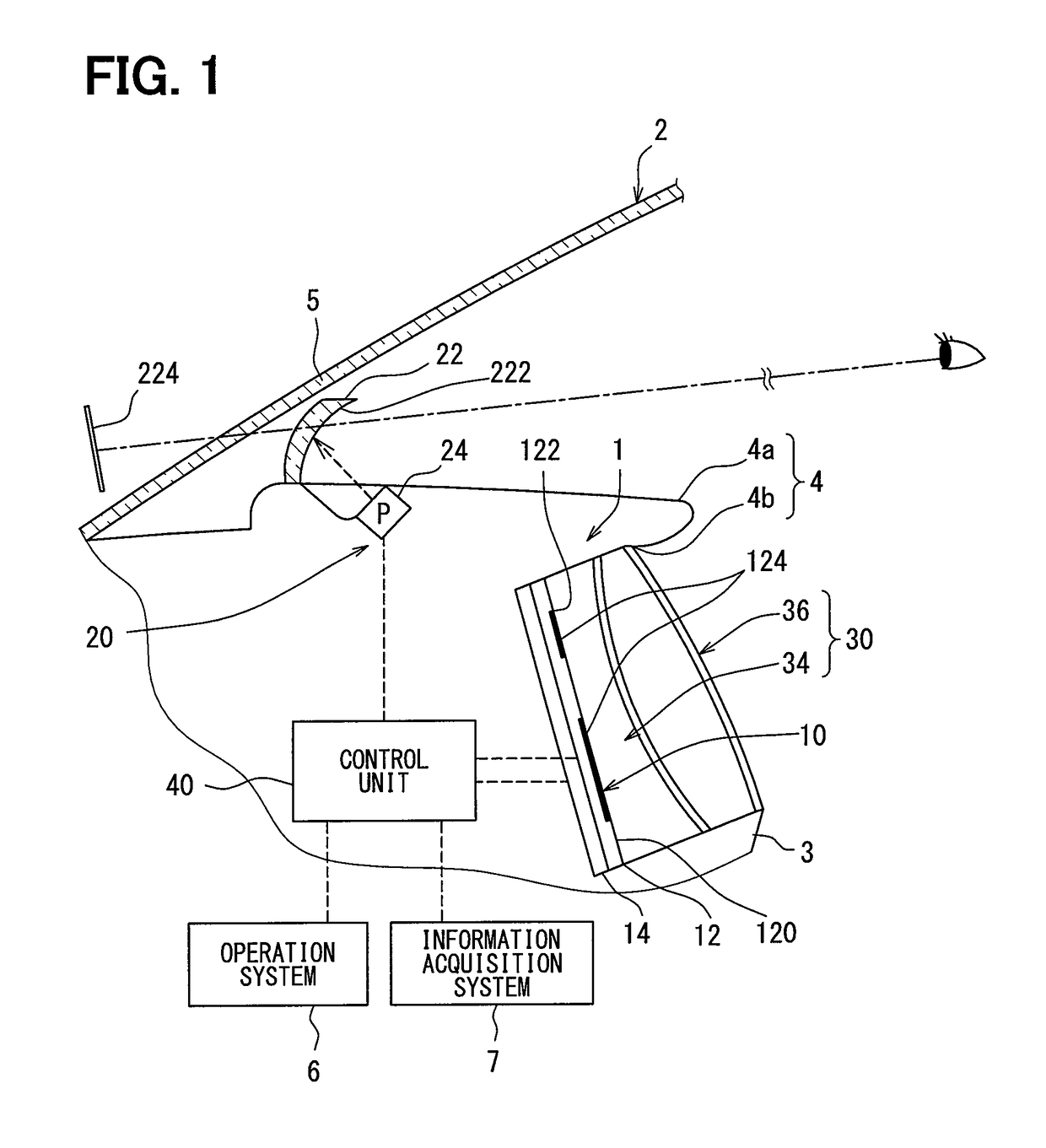
[0040]As illustrated in FIG. 1, a display device 1 for a vehicle is provided in front of a driver seat inside a vehicle 2. The display device 1 displays vehicle information associated with the vehicle 2 in such a manner that the vehicle information is visible to a user on the driver seat. The display device 1 includes a first display unit 10, a second display unit 20, a light emission unit 30, and a control unit 40. Note that an upper direction, a lower direction, and a lateral direction in the following description respectively indicate an upper direction, a lower direction, and a lateral direction inside the vehicle 2 with respect to a horizontal plane.

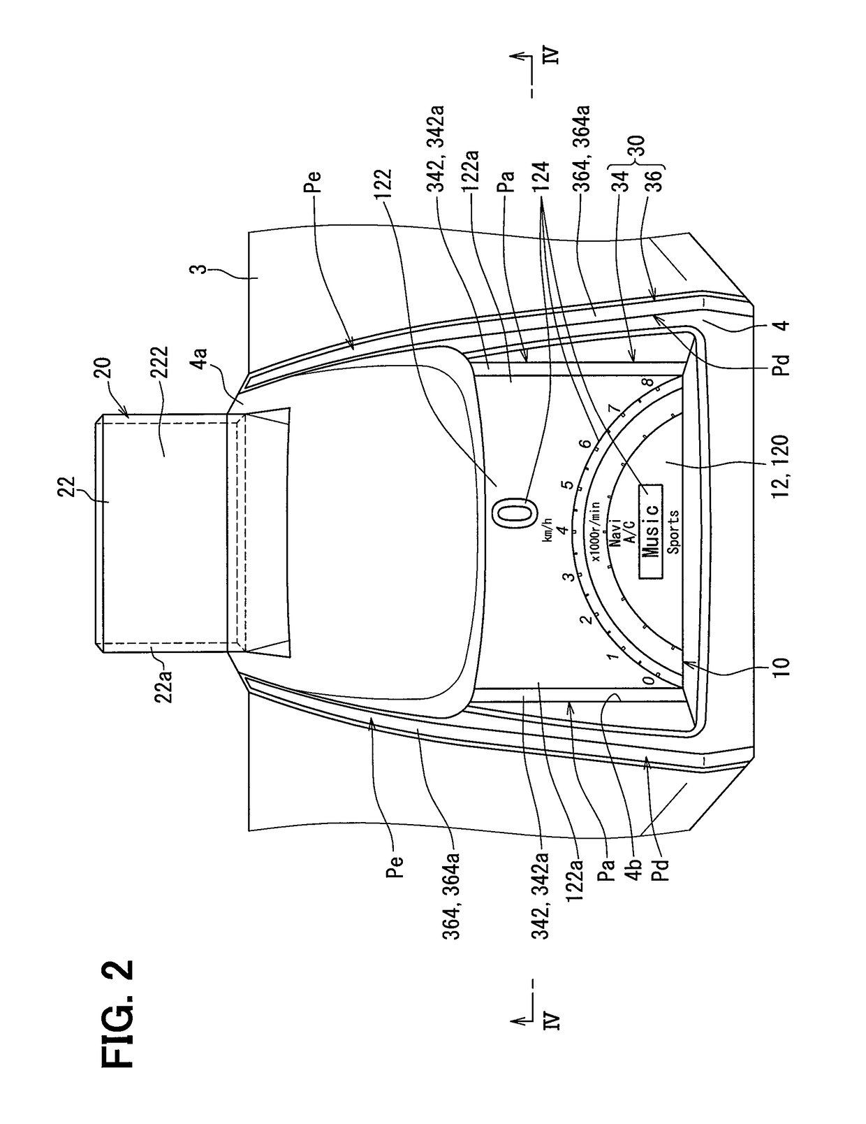
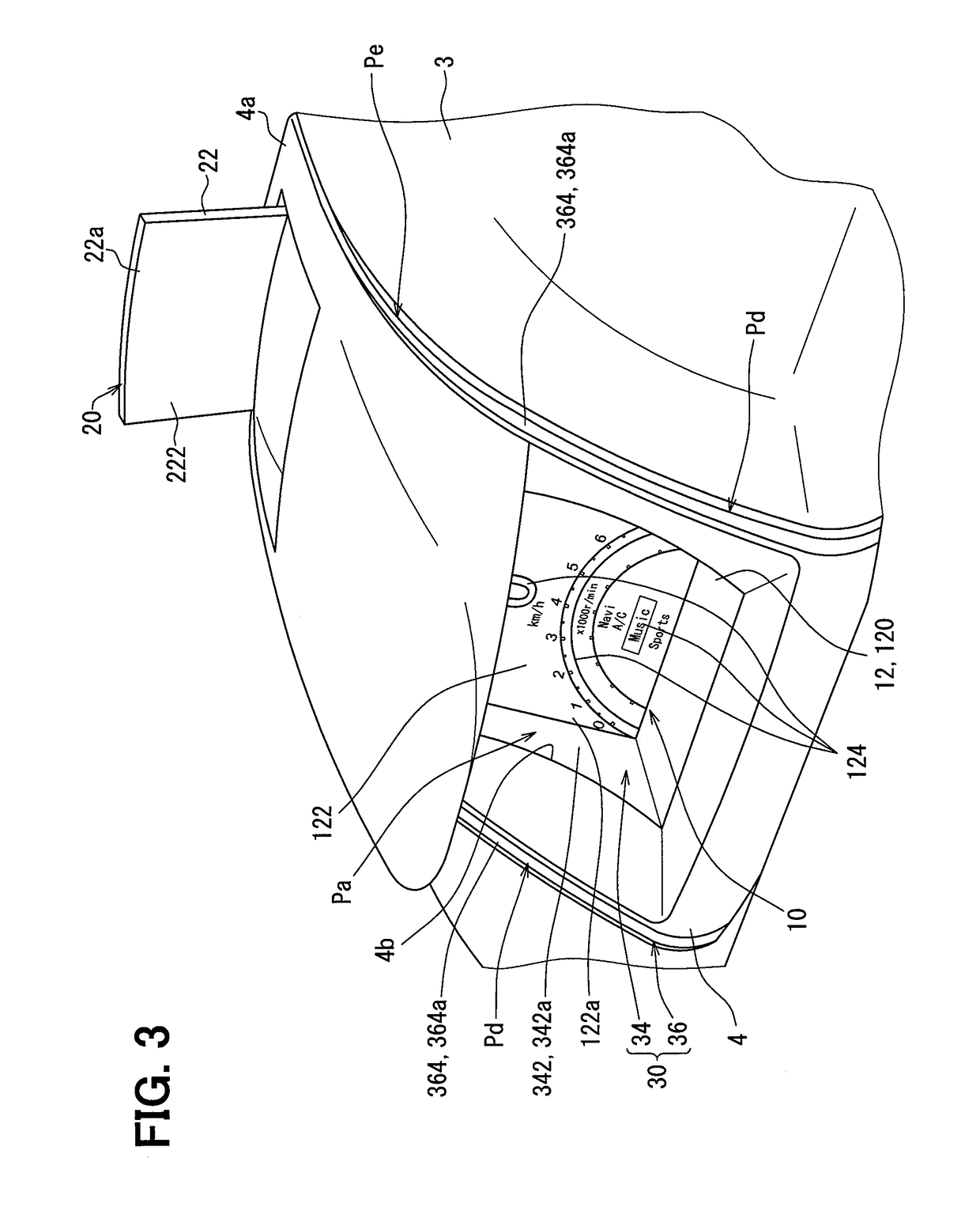
[0041]As illustrated in FIGS. 1 to 4, the first display unit 10 is housed in a hood 4 provided on an instrument panel 3, and located in front of the driver seat inside the vehicle 2. The first display unit 10 includes a display panel 12 configured by a liquid crystal panel or an organic EL panel, for example. The display panel 12 in...

second embodiment

[0103]A second embodiment is a modified example of the first embodiment. The control unit 40 in the guiding operation mode Md of the second embodiment change light emission areas 2346 and 2366 by controlling the adjacent light sources 340 and the separate light sources 360 as illustrated in divisional figures of (a), (b), (c), (d), (e), (f), and (g) of FIG. 20.

[0104]More specifically, the size of the adjacent light emission area 2346 in each of the adjacent light guide bodies 342 gradually increases in the guiding direction Dd from the first display portion 122 toward the second display portion 222. In this case, particularly the size of the adjacent light emission area 2346 in each of the adjacent light guide bodies 342 temporarily increases in a range from a lower end in (a) of FIG. 20 to an upper end in (c) of FIG. 20 at the adjacent positions Pa. Furthermore, the size of the light emission area 2346 in each of the adjacent light guide bodies 342 decreases in a range from a lower...


PUM


Abstract

A display device for a vehicle includes: a first display unit that displays a real image of first information in a first display portion; and a second display unit that displays a virtual image of second information in a second display portion by projecting an optical image to the second display portion, the second display portion being disposed above the first display portion and transmitting an external image. The display device includes: a light emission unit located adjacent to a side of the first display portion to form a light emission area; and a control unit that changes the light emission area in a guiding direction from the first display portion toward the second display portion during a linking period for linking a particular virtual image display of the second information with a real image display of the first information.

Description

CROSS REFERENCE TO RELATED APPLICATION-APPLICATIONS[0001]This application is a U.S. National Phase Application under 35 U.S.C. 371 of International Application No. PCT / JP2016 / 002042 filed on Apr. 15, 2016 and published in Japanese as WO 2017 / 006503 A1 on Jan. 12, 2017. This application is based on and claims the benefit of priority from Japanese Patent Application No. 2015-138055 filed on Jul. 9, 2015. The entire disclosures of all of the above applications are incorporated herein by reference.TECHNICAL FIELD[0002]The present disclosure relates to a display device for a vehicle to display vehicle information related to the vehicle.BACKGROUND ART[0003]A vehicle display device is widely known, which displays vehicle information on each of a first display portion and a second display portion.[0004]More specifically, a vehicle display device disclosed in Patent Literature 1 includes a display screen area that corresponds to a second display portion capable of transmitting an external im...

Claims


Application Information

Patent Timeline
Patent Type & Authority Patents(United States)
IPC IPC(8): G06F3/14G09G5/12G09G5/14H04N5/74B60K35/00B60K37/02G02B27/01G06T11/60G09G5/10
CPCG09G5/12B60K37/02G02B27/01G02B27/0101G06F3/1423G06T11/60G09G5/10G09G5/14H04N5/74B60K35/00G09G2380/10B60K2350/1072B60K2350/203B60K2350/2052B60K2350/2065B60K2370/1529B60K2370/177B60K2370/334B60K2370/155B60K2370/31B60K2370/33G02B27/0149G02B2027/0165H04N9/3179G03B21/56H04N9/31
Inventor FUJITA, KATSUMITAMURA, SATORUTOYOTA, MASASHITANE, SEIGO
Owner DENSO CORP
Why Eureka
Try Eureka