
Low power mode

a low-power mode and power management technology, applied in the direction of data processing power supply, instruments, high-level techniques, etc., can solve the problems of limited functionality, unused portion of the battery capacity, and reduced peripheral usage, so as to reduce peripheral usage and extend the useful operation of the electronic device.

Inactive Publication Date: 2019-03-12
APPLE INC
View PDF53 Cites 6 Cited by
  • Summary
  • Abstract
  • Description
  • Claims
  • Application Information

AI Technical Summary

Benefits of technology

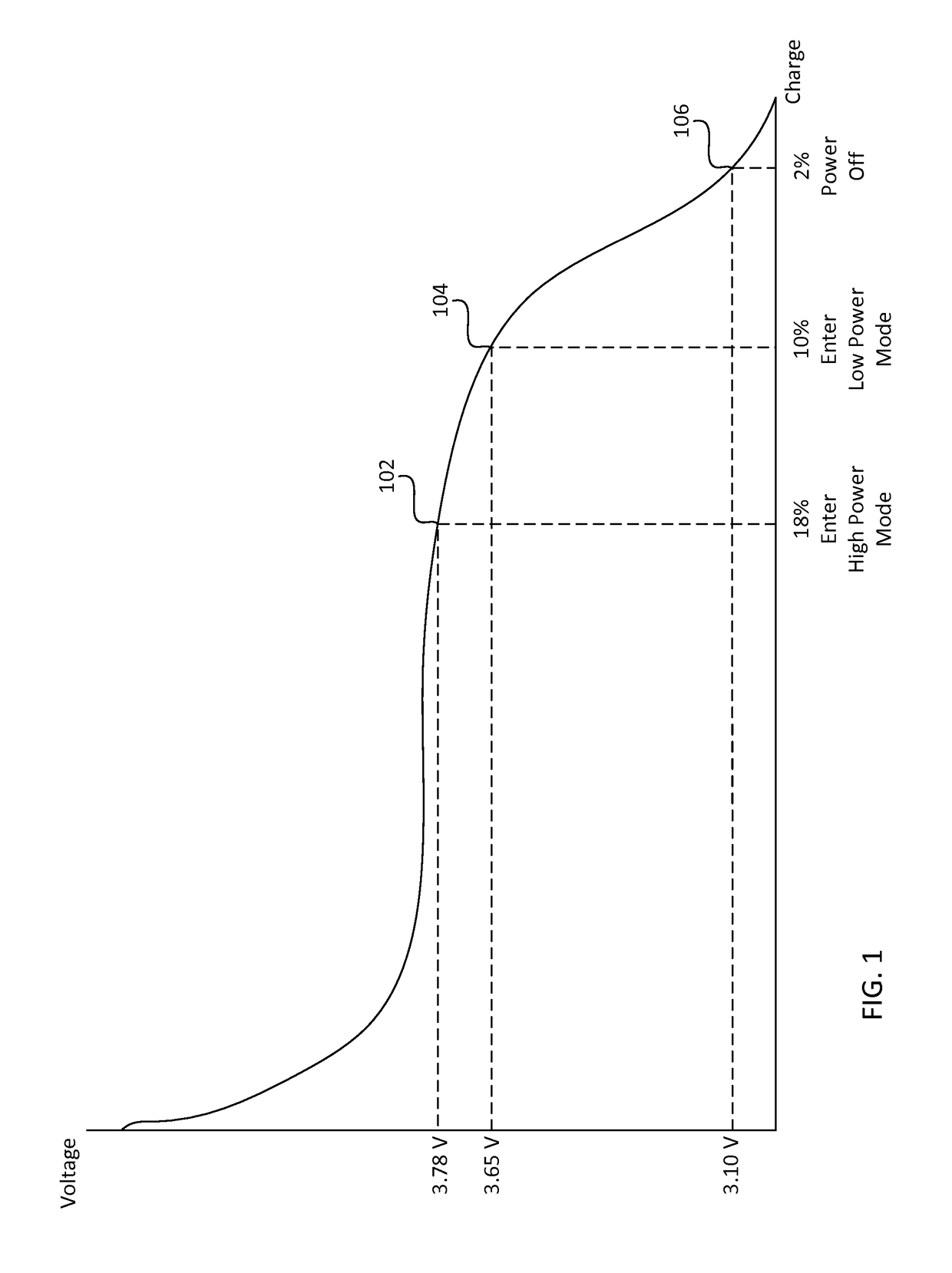
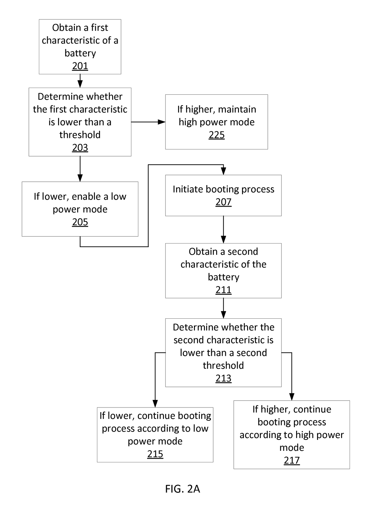
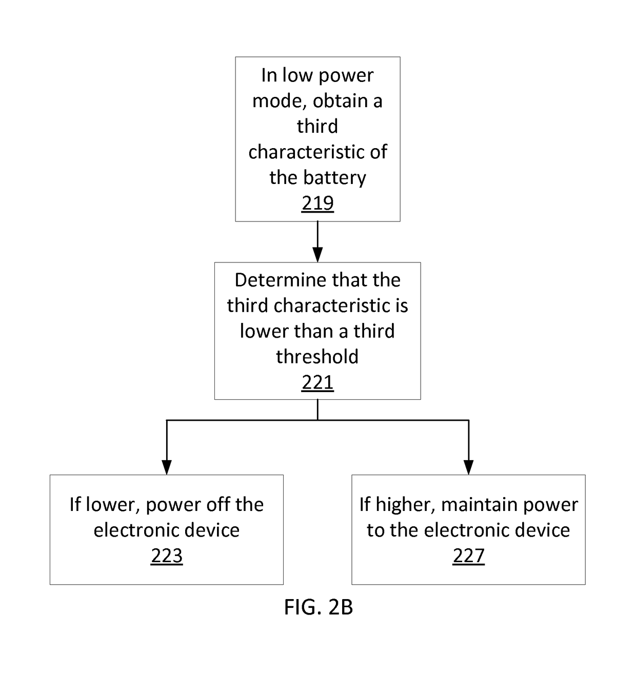
[0005]Examples of the disclosure are directed to a method of, after hitting a voltage threshold, such as an UVLO threshold, rebooting an electronic device in a low power mode having a different, lower UVLO threshold, such that the device can continue to be used. For example, in a high power mode, the device may be capable of a number of functionalities of a modern portable electronic device, such as network access, the ability to run applications, Bluetooth connections, etc. In a low power mode, the device may be enabled for a limited set of functions. For example, the device may only be able to check and display a current time, play an alarm sound at a predefined time, perform near field communication (NFC) transactions / payments, among other possibilities described herein. The limited functionality and reduced usage of peripherals in the low power mode may prevent the battery from experiencing peaks in current level that may be problematic at relatively low levels of voltage. Operation in a lower power mode also may extend the useful operation of an electronic device. An electronic device may be any electronic device such as a desktop computer, portable multifunction device (e.g., a smartphone), wearable device, tablet computer, etc.

Problems solved by technology

If the electronic device is powered down, e.g., when the voltage falls to an undervoltage lockout (UVLO) threshold, a portion of the battery's capacity may remain unused.
The limited functionality and reduced usage of peripherals in the low power mode may prevent the battery from experiencing peaks in current level that may be problematic at relatively low levels of voltage.

Method used


Image

  • Low power mode
  • Low power mode
  • Low power mode

Examples


Embodiment Construction

[0012]In the following description of examples, reference is made to the accompanying drawings which form a part hereof, and in which it is shown by way of illustration specific examples that can be practiced. It is to be understood that other examples can be used and structural changes can be made without departing from the scope of the disclosed examples.

[0013]Examples of the disclosure are directed to a method of, after hitting a voltage threshold, rebooting an electronic device in a low power mode having a lower voltage threshold, such that the device can continue to be used. An undervoltage lockout (UVLO) threshold is presented for the sake of example, but other and / or additional thresholds can be used. For example, in a high power mode, the device may be capable of a number of functionalities of a modern portable electronic device, such as network access, the ability to run applications, Bluetooth connections, etc. In a low power mode, the device may only be able to perform a ...


PUM


Abstract

Examples of the disclosure are directed to a method of, after hitting a UVLO threshold, rebooting an electronic device in a low power mode having a lower UVLO threshold, such that the device can continue to be used past the first UVLO threshold. For example, in a high power mode, the device may be capable of a number of functionalities of a modern portable electronic device, such as network access, the ability to run applications, Bluetooth connections, etc. In a low power mode, the device may only be able to check and display a current time, play an alarm sound at a predefined time, perform near field communication (NFC) transactions / payments, among other possibilities described herein. The limited functionality and reduced usage of peripherals in the low power mode may prevent the battery from experiencing peaks in current level that may be problematic at relatively low levels of voltage.

Description

CROSS-REFERENCE TO RELATED APPLICATIONS[0001]This application is related to and claims the benefit of U.S. Provisional Application Ser. No. 62 / 033,819, filed Aug. 6, 2014, entitled “Low Power Mode”, and to U.S. Provisional Application Ser. No. 62 / 034,103, filed Aug. 6, 2014, entitled “Reduced-Size User Interfaces for Battery Management,” the entire disclosure of which is herein incorporated by reference in their entirety for all purposes.FIELD OF THE DISCLOSURE[0002]This relates generally to power management of an electronic device.BACKGROUND OF THE DISCLOSURE[0003]An electronic device may require a power supply, such as a battery. Further, the electronic device may require that the power supply have a certain minimum voltage in order to function properly. For example, a battery may not be able to sustain peaks in current level when the voltage drops below a certain level. Accordingly, an electronic device may monitor the voltage of its power supply and power down when the voltage f...

Claims


Application Information

Patent Timeline
Patent Type & Authority Patents(United States)
IPC IPC(8): G06F1/32G06F1/3212G06F1/3296G06F9/4401
CPCG06F1/3296G06F1/3212Y02D50/20Y02D10/172Y02D10/174G06F9/4401Y02D10/00Y02D30/50
Inventor ANDREWS, JONATHAN J.DE LA CROPTE DE CHANTERAC, CYRILKIM, EUGENE
Owner APPLE INC
Learn More