Submerged combustion melters and methods of feeding particulate material into such melters

a technology of melters and particulates, applied in the field of submerged combustion melters, can solve the problems of reducing melt quality, affecting the quality of melt, so as to minimize the entrainment of particulate feed materials, improve quality, and maximize mixing

Active Publication Date: 2019-03-19
JOHNS MANVILLE CORP
View PDF483 Cites 3 Cited by
  • Summary
  • Abstract
  • Description
  • Claims
  • Application Information

AI Technical Summary

Benefits of technology

[0008]In accordance with the present disclosure, methods of maximize mixing of particulate feed materials into molten mass within a SCM, and / or minimizing entrainment of particulate feed materials in SCM exhaust are described. “Particulate feed materials” may include glass batch or other particulate matter (organic or inorganic), fed separately or in combination (mixed, semi-mixed, or agglomerated). Methods and systems wherein particulate feed materials are fed into a “splash zone” or “splash region” inside the SCM in order to improve the quality (mainly determined by homogeneity) of the melt from an SCM, and / or or reduce feedstock loss through SCM exhaust, are described that may reduce or eliminate problems with known SCM operation to produce molten glass and other non-metallic inorganic materials, such as mineral wool.

Problems solved by technology

The introduction of high flow rates of products of combustion of the oxidant and fuel into the molten material, and the expansion of the gases during submerged combustion (SC), cause rapid melting of the feedstock and much turbulence and foaming.
While aggressive mixing and turbulence are desired for reducing time to melt feedstock, this splashing (where molten material actually breaks away from the turbulent surface and travels upward and then falls back down into the vitreous mass by gravity, or strikes the ceiling or walls of the SCM and drips back down into the molten mass, or solidifies thereon) is problematic as it causes at least some of the particulate batch feed to be splashed to undesired areas within the SCM, and is thus wasteful and decreases melt quality.
In known SCMs, raw batch or other particulate material is typically fed from above the vitreous molten material in the SCM, either from feed inlets in the ceiling or the walls above the splash region, or fed by or fed by mass movers such as screws or augers through a wall with the expectation that all of the batch will penetrate into the turbulent molten mass inside the SCM, What the present inventor has discovered, however, is that the aggressive movement of the molten vitreous material causes even more violent splashing than previously recognized, causing some of the particulate materials to reach undesired areas of the SCM, such as the ceiling, reducing residence time and / or not allowing for a homogeneous melting of raw materials.
Some of the batch or other particulate material may also become entrained in the exhaust gases causing additional waste.
While some of this may be recycled to the feed, it is inefficient from an energy standpoint.

Method used


Image

  • Submerged combustion melters and methods of feeding particulate material into such melters
  • Submerged combustion melters and methods of feeding particulate material into such melters
  • Submerged combustion melters and methods of feeding particulate material into such melters

Examples


Embodiment Construction

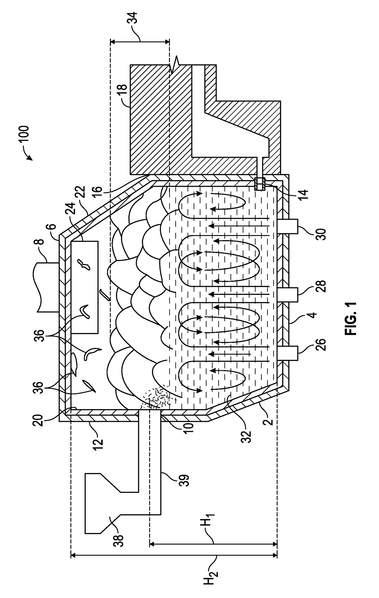
[0025]In the following description, numerous details are set forth to provide an understanding of the disclosed systems, apparatus, and methods. However, it will be understood by those skilled in the art that the systems, apparatus, and methods covered by the claims may be practiced without these details and that numerous variations or modifications from the specifically described embodiments may be possible and are deemed within the claims. For example, wherever the term “comprising” is used, embodiments and / or components where “consisting essentially of” and “consisting of” are explicitly disclosed herein and are part of this disclosure. An example of “consisting essentially” is with respect to the total feed to an SCM: a feed consisting essentially of particulate feedstock means there may be a minor portion of feed that is not particulate feedstock, such as rock used to make mineral wool. An example of “consisting of” may be a feedstock made up of only particulate feedstock, or o...


PUM

PropertyMeasurementUnit
particle sizeaaaaaaaaaa

Abstract

Methods of melting particulate feedstocks in a submerged combustion melter employing an arrangement of one or more submerged combustion burners emitting combustion products into turbulent molten material. Operating the burners such that there is established a turbulent melting region extending vertically from the floor to a splash region, the splash region extending vertically between the turbulent melting region and a head space region, the head space region extending vertically between the splash region and the melter ceiling, the ceiling positioned above the floor a height H2. Feeding the particulate feedstock into the splash region through one or more inlet ports, the inlet ports positioned at a height H1 measured from the floor, where H1 / H2 ranges from about 0.33 to about 0.67. The SCM may have a baffle extending from the ceiling into the splash region. A particulate feedstock conduit may be employed, having an exit port in the splash region.

Description

BACKGROUND INFORMATION[0001]Technical Field[0002]The present disclosure relates generally to the field of submerged combustion melters and apparatus, and methods of use, and more specifically to submerged combustion melters, and methods of operating same, particularly for melting glass-forming materials, mineral wool and stone wool forming materials, and other predominantly non-metallic inorganic materials.[0003]Background Art[0004]A submerged combustion melter (SCM) may be employed to melt glass batch and / or waste glass materials (including waste glass materials that have an organic coating) to produce molten glass, or may melt mineral wool feedstock (basalt rock, sometimes referred to as lava rock) to make mineral wool, by passing oxygen, oxygen-enriched mixtures, or air along with a liquid, gaseous and / or particulate fuel (some of which may be in one or more of the feedstock materials), directly into a molten pool of glass or other material, usually through burners submerged in a...

Claims


Application Information

Patent Timeline
Patent Type & Authority Patents(United States)
IPC IPC(8): C03B5/235C03B5/04C03B3/00
CPCC03B5/2356C03B5/04C03B3/00C03B2211/23
Inventor FAULKINBURY, ALBERT PATRICKHUBER, AARON MORGAN
Owner JOHNS MANVILLE CORP
Why Eureka
Try Eureka