Thermoregulation interface pack and assembly

a technology of interface packs and thermoregulation, applied in the direction of therapeutic heating, therapeutic cooling, contraceptive devices, etc., can solve the problems of inability to control the flow, location or heat transfer of fluids in the interface pack, and the inability to control the fluid position in the interface pack

Inactive Publication Date: 2015-11-26
PHYSIOLAB TECH
View PDF22 Cites 0 Cited by
  • Summary
  • Abstract
  • Description
  • Claims
  • Application Information

AI Technical Summary

Benefits of technology

[0010]By contrast, the structure taught herein provides, at the points of path inversion, zones in the fluid conduit of zero apparent fluid flow but without actually stopping the flow of fluid in the conduit. More specifically, fluid flowing in the conduit has to invert its flow direction due to the path inversions and will thus have a point of zero instantaneous speed. The flow restrictors create turbulence in the fluid at the points of path inversion, which ensure that the fluid continues to move rather than stagnate, avoiding the generation of laminar fluid flow and maximising the mixing of fluid at the points of path inversion, thereby optimising the energy transfer to or from the fluid through the walls of the interface pack.
[0015]In the preferred embodiment, the or each conduit is in the form of a series of spirals with each spiral curving in opposing directions either side of a point of path inversion. This structure has been found to be the most effective in that it creates a series, in the preferred embodiment an array, of thermo-regulated zones in the interface pack. This shape of the conduit has been found to create very effective heat transfer zones in the pack, much better able to transfer heat to and from the fluid in the pack and thus to and from the patient. Moreover, it has been found that this shape can provide rapid changes in fluid temperatures in the pack, enabling it to be used in treatments which provide sophisticated and variable temperature profiling, not possible with prior art structures. This shape is also able to transmit treatment pressure to the patient, generated by the pressure of the fluid supply as described below.
[0017]Advantageously, the interface pack includes first and second layers forming the interface pack, the second layer providing the treatment surface and the first layer providing an outer layer of the interface pack, wherein the first layer has a stiffness greater than a stiffness of the second layer at least in the treatment zone. This feature ensures than pressure of fluid in the interface pack will cause the second layer, and hence the treatment surface, to deform in preference to the first surface, thereby providing enhanced contact of the interface pack against a patient's skin. Advantageously, the second layer is made of a conformable material. In the preferred embodiment, the second layer is thinner than the first layer, leading to its increased flexibility. Other embodiments have the first and second layers of different materials, which may or may not be of different thicknesses.
[0020]It is preferred that the pressure relief valves are covered by the insulation layer; which results in any loss of fluid from the interface pack as a result of opening of the pressure relief valves being held by the insulation layer. Advantageously, the insulation layer is fluid tight and is separate from the first layer at least in the locations of the pressure relief valves, so as to create chambers for holding pressure released fluid. This ensures that fluid does not leak out of the interface pack and thus that the interface pack can remain operational even after opening of one or more of the pressure relief valves.
[0022]In an embodiment, there is provided a gel layer overlying the treatment surface and for contact with a patient. The gel layer promotes good thermal contact between the interface pack and the patient's skin.

Problems solved by technology

The inventors have found that some of the principal problems of fluid based thermoregulation interface pack include that such packs do not adequately control the flow, location or heat transfer to or from the fluid in the interface pack.
For example, with interface packs having relatively large fluid chambers, it is not possible to control the location of fluid in the interface pack, particularly when it is pressed against a patient's body, nor the flow of fluid in the interface pack.
This results in the generation of zones of the interface pack which do not provide adequate energy transfer to and from the patient.
With interface packs which provide continuous fluid flow through the interface pack, for example through conduits, much of the available energy is wasted by being transferred through the moving fluid rather than being released for treatment.
Moreover, such interface packs do not resolve the problem of pressure on the pack altering the flow of fluid to create ineffective zones in the interface pack.

Method used


Image

  • Thermoregulation interface pack and assembly
  • Thermoregulation interface pack and assembly
  • Thermoregulation interface pack and assembly

Examples


Embodiment Construction

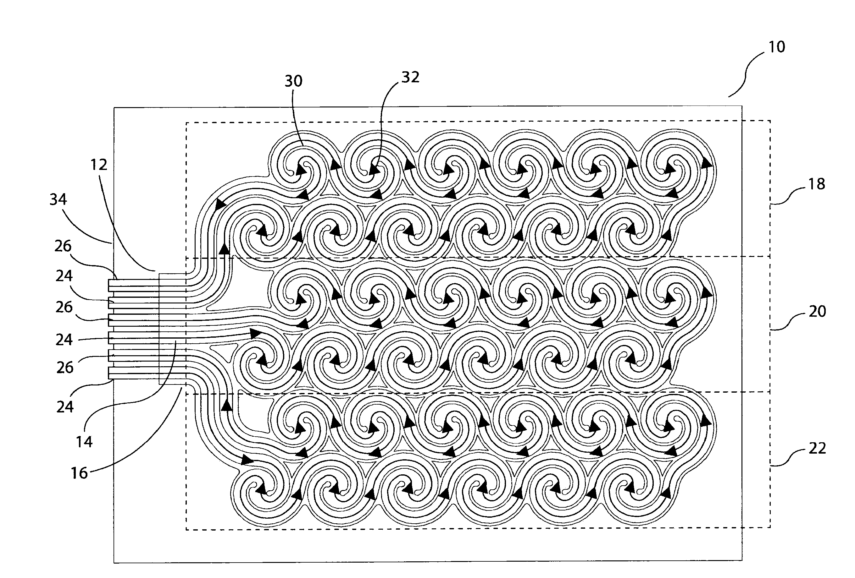
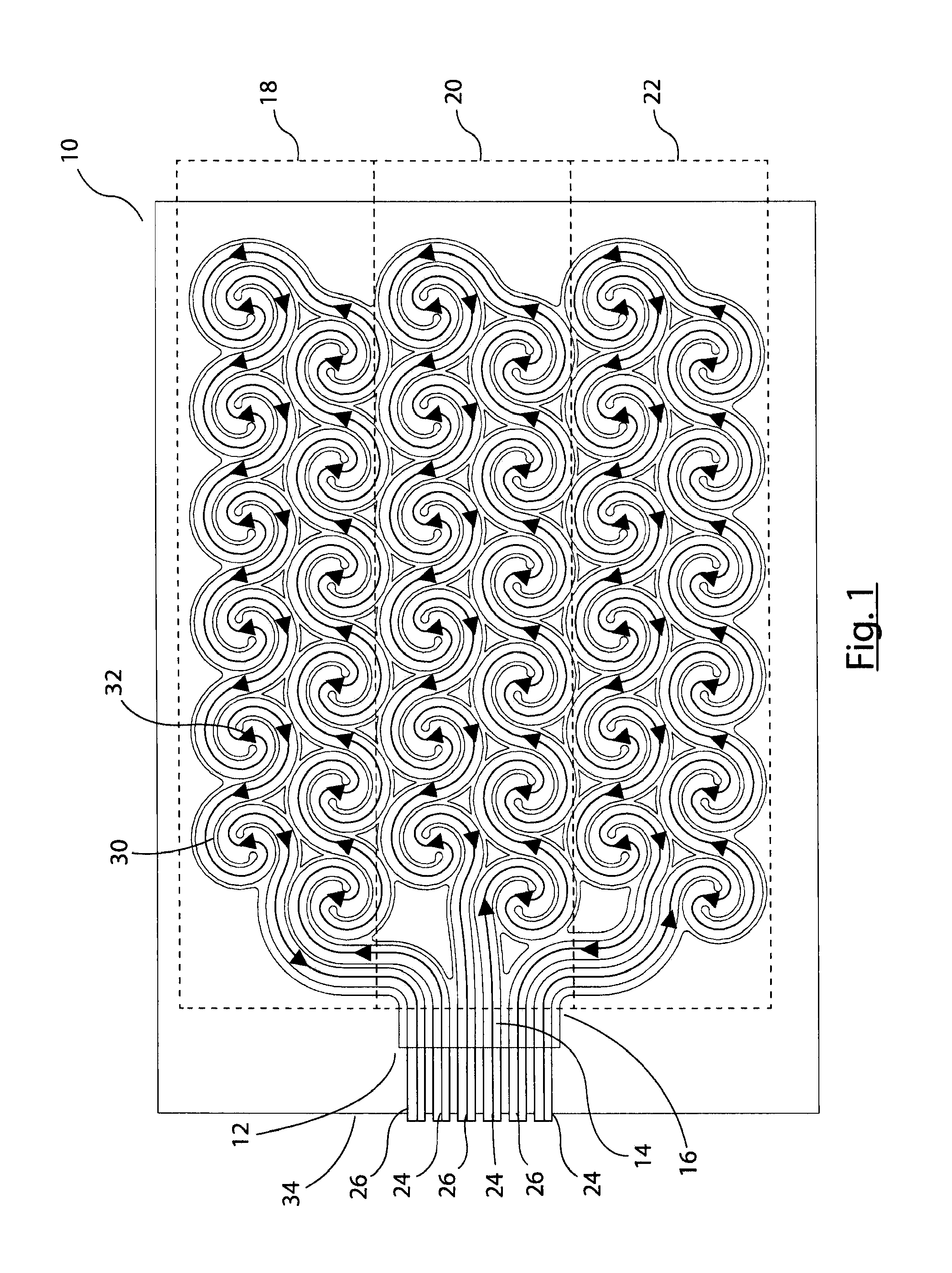
[0037]Described below are various embodiments of temperature regulated interface pack, which is designed to be conformed around a part of a patient's body such as a limb or the like. The teachings therein, however, are not limited to an interface pack of a specific form, as the interface pack could have any shape suitable for the particular treatment desired for a patient. In some embodiments, the interface pack could be in the form of a sleeve or garment into which part of the patient's body to be treated can be inserted.

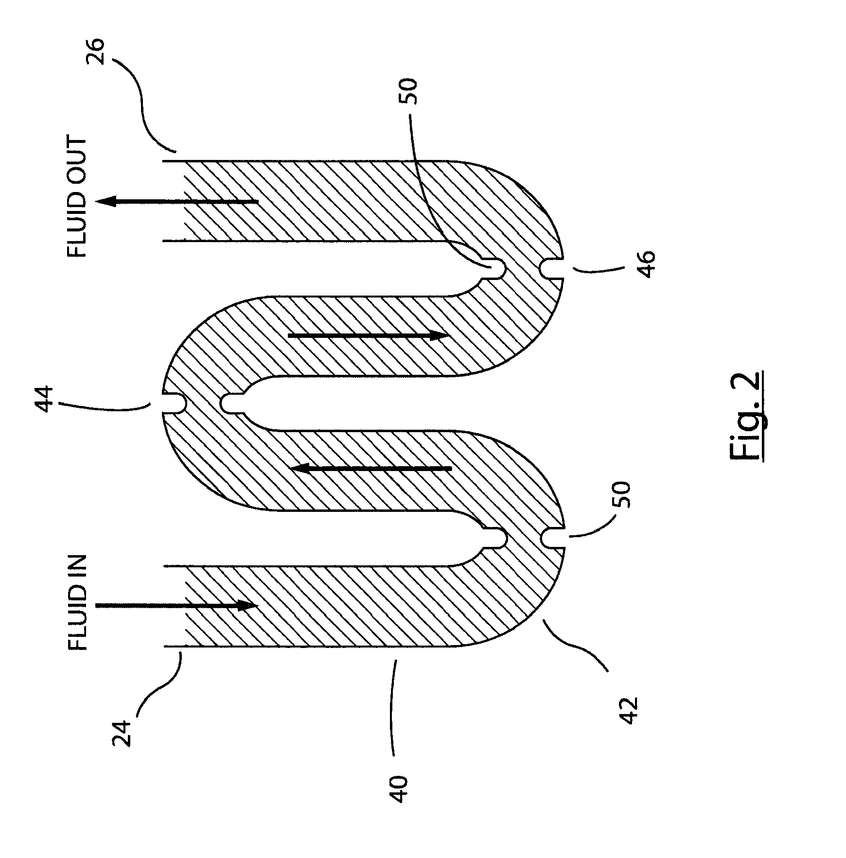
[0038]The interface pack is intended for use with a temperature regulation system which includes a pump, heating and / or cooling elements for heating fluid which is then pumped via the pump into the conduits of the interface pack. It is envisaged that such a system would provide one or more temperature sensors able to sense the temperature of fluid in the interface pack or the temperature of the interface pack. Such sensors may be provided within the system or as pa...


PUM


Abstract

A thermoregulation interface pack (10) for the treatment of physical injuries and disorders includes a plurality of conduits (12-16) providing separate feed and return through channels (24, 26), are arranged in each conduit in a plurality of spiral shapes (30), each of which provides a fluid path inversion (32). At the fluid path inversion (32) the conduits (12-16) are provided with flow constrictors (50). This shape of the conduits (12-16) provides an array of zones (30) of zero fluid speed which optimises energy transfer between the interface pack (10) and the patient. The interface pack (10) is preferably formed of two layers (60, 62) of material of which the inner or contact layer (62) is made of a more conformable material than the overlying or upper layer (60), causing the contact layer (62) to deform to a greater extent than the upper layer (60), thereby to increase surface contact with the patient. The interface pack (10) can be provided with an insulating layer (70), with pressure release valves (88) and with a compression sleeve (100).

Description

TECHNICAL FIELD[0001]The present invention relates to a thermoregulation interface pack and assembly for the treatment of physical injuries and disorders. The preferred embodiments are also able to effect pressure treatment on a patient.BACKGROUND ART[0002]There are numerous instances where it is desired to effect a thermal treatment on a patient. For example, this may be to treat a physical injury, such as of the muscles, ligaments, tendons and the like. It may also be useful in treating skin injuries, as well as illnesses such as infections and the like.[0003]Thermal treatments of this type have been known for many years, in their simplest form being ice packs. Subsequently, heat generating packs were developed, typically in the form of a pouch of chemical material which can be made to react exothermically and thereby to release heat. These devices are intended to cool or heat, as appropriate, a part of a person's body in order to alleviate inflammation, pain suffered by the patie...

Claims


Application Information

Patent Timeline
Patent Type & Authority Applications(United States)
IPC IPC(8): A61F7/02
CPCA61F7/02A61F2007/0054A61F2007/0273A61F2007/0233A61F2007/0249A61F2007/0228A61F2007/0091A61F2007/0244
Inventor ROSE, NICHOLASHASKINS, MARK
Owner PHYSIOLAB TECH
Why Eureka
Try Eureka