Computer system for measuring real time position of a plurality of animals

a computer system and real-time position technology, applied in the field of computer systems for measuring real-time position of a plurality of animals, can solve the problem that the computer system can be totally overloaded in handling position data, and achieve the effect of preventing any overloading of the computer system, affecting accuracy, and high success in radio communication

Active Publication Date: 2019-03-19
GEA FARM TECH
View PDF29 Cites 1 Cited by
  • Summary
  • Abstract
  • Description
  • Claims
  • Application Information

AI Technical Summary

Benefits of technology

[0011]In a further preferred embodiment position data is received is processed in the order the data was received, which data is placed in a First-In-First-Out stack (FIFO), where the oldest measurements are processed first. The use of a First-In-First-Out stack in the computer system can have the result that the RTLS system can deliver data independent of the speed of operation in the computer system. In some situations, the RTLS-system might sense a lot of data, because there is a high success in radio communication where a few seconds later there is some disturbance in the radio communication and no data is transmitted. In a situation where no data is received or a number of data is reduced, the processor can still operate at full speed, because data are always available in the First-In-First-Out stack.
[0012]In a further preferred embodiment the system processes several strings of location information at the same time, where the exact number of parallel processing threads is setup in a configuration file. The performance of the code and the PC is sufficient, so that the data of the current installations can be processed upon arrival. Therefore it has so far not been necessary to implement an overflow protection mechanism to discard old data in case of delays. For larger systems, it will instead be possible to use a computer which can perform the processing in more parallel strings and therefore any overloading of the computer system will still be prevented.
[0013]In a further preferred embodiment the system comprises a Movement Module, which Movement Module receives time stamped RTLS positioning data, which Movement Module generates a output as a point with a zone attribute, which Movement Module comprises noise reduction filters at least such as Median and Exponentially Weighted Moving Average (EWMA). The median is computed on each data point coordinate in a moving window of N data points. This means that every data point is replaced with the median of this data point and the N−1 previous data points. The median is configured with one parameter, which is the number of data points in the window. A large number of data points will make the measurements appear smoother, but may also affect the accuracy. The number of data points to mediate is configured differently for each farm and for each of the two calculation tracks. The EWMA is configured with the exponential factor to apply to old data points. This may likewise be configured differently for each farm and for each of the two calculation tracks. The EWMA algorithm does not reduce the amount of location data points, but adjusts the current point according to the earlier measurements.
[0014]Hereby is achieved that very precise measurement of the tags placed on the animals is performed after the EWMA algorithm is performed. In that way even small deviations in position of animals can be used for the analysis of the animal activity, and this measurement will in no way conflict the fast data processing that is used for an overview of the exact position of animals.

Problems solved by technology

Because of the number of data that is received from different sensors communicated from tags where a high number of animals together with a relative high number of reference tags are transmitting data, the computer system can be totally overloaded in handling position data.

Method used


Image

  • Computer system for measuring real time position of a plurality of animals
  • Computer system for measuring real time position of a plurality of animals
  • Computer system for measuring real time position of a plurality of animals

Examples


Embodiment Construction

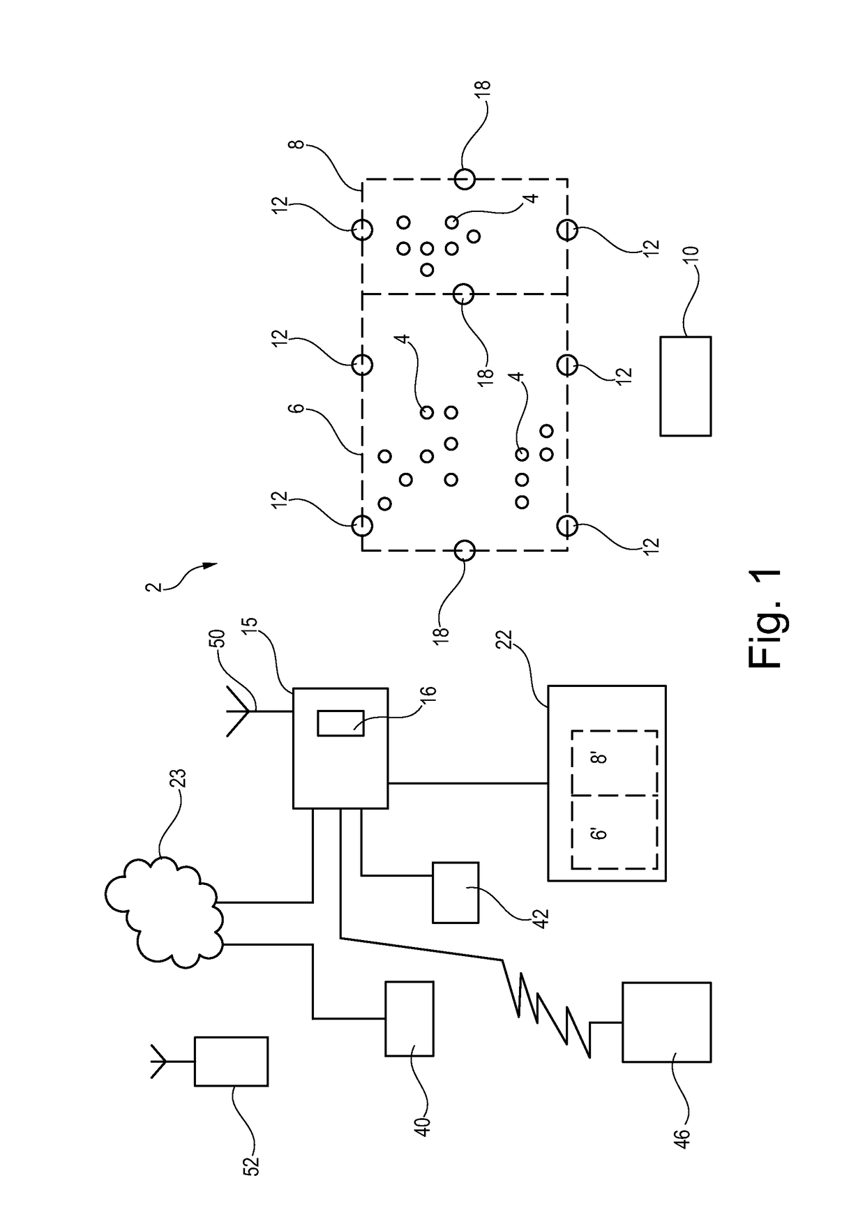
[0044]FIG. 1 discloses a possible embodiment for a system 2, which system comprises a restricted area 6 and / or a restricted sub area 8. In the restricted area 6,8 is indicated animals 4. These animals all carry a transmitter tag 10 which in a preferred version transmit a signal with time intervals controlled in the software of the tag. That means the tag 10 may transmit a signal one ore more times per second. The system 2 further comprises a plurality of sensors 12 here indicated at the border of the restricted area 6,8. Further is indicated fixed reference tags 18 here indicated in the middle of the restricted area 6,8. The system further comprises a farm server 15 which farm server comprises a position detection system 16. The system 2 generates a map 22 which map 22 shows the restricted area 6′,8′ and not shown, but in practice indicating the animals 4 at the map. The farm server 15 is further connected to the internet 23 and through the internet 23 there is a connection to any c...


PUM


Abstract

The present invention relates to a computer system for measuring real time position of a plurality of animals, which system receives input from a plurality of sensors, communicating with at least tags carried by the animals, which system based of measurement of delay in radio communication calculates the actual position of the animals. It is the first object of the invention to achieve real time position of animals in a limited area. A further object is based of the real time position to analyze the behavior of each of the animals. The sensors further performs communication with a plurality of reference tags, and performs a calibration of the real time position measured by the system, which system comprises a CPU with at least two cores, which system divides the data processing in a first real time position processing in the first core of the processor, and into a second processing of the activity of the animals performed in the second core of the processor. By using fixed reference tags together with tags, it the computer system performs an automatic calibration of all received signals from animals.

Description

FIELD OF THE INVENTION[0001]The present invention relates to a computer system for measuring real time position of a plurality of animals, which system based of real time position of the animals determine behaviour of the animals, which system receives input from a plurality of sensors, which sensors communicates at least with radio receiver / transmitter tags carried by the animals, which system based of measurement of delay in radio communication between the radio receiver / transmitter tags and the sensors calculates the actual position of the animals.BACKGROUND OF THE INVENTION[0002]WO2010DK50065 discloses a system and a method for detecting the behaviour of a number of animals, such as cattle, where each animal carries at least a number of detectors, which detectors are communicating with at least a first processor carried by the animal, which first processor further communicates with a central processor. The object of the invention is to detect animal behaviour and transmit data c...

Claims


Application Information

Patent Timeline
Patent Type & Authority Patents(United States)
IPC IPC(8): A01K29/00G01S5/02A01K15/02G01S5/14
CPCG01S5/0252A01K15/023G01S5/14G01S5/021A01K29/005G01S2205/01
Inventor SLOTH, KAREN HELLEFREDERIKSEN, DANIEL
Owner GEA FARM TECH
Why Eureka
Try Eureka