Eureka AIR delivers breakthrough ideas for toughest innovation challenges, trusted by R&D personnel around the world.

Full-color light emitting diode display having improved luminance and method of manufacturing the same

Active Publication Date: 2019-03-19
SAMSUNG DISPLAY CO LTD
View PDF9 Cites 0 Cited by
  • Summary
  • Abstract
  • Description
  • Claims
  • Application Information

AI Technical Summary

Benefits of technology

The present invention provides a full-color LED display with uniform luminance and improved color reproduction. The method of manufacturing ensures that the intensity of light emitted is similar between pixels or subpixels and improves intensity in a specific wavelength band. This results in excellent color reproduction and reduced color distortion.

Problems solved by technology

A full-color LED display capable of directly displaying an image through LEDs is not commercially available.
Since there are technical limitations in a process of mounting and arranging LEDs in a panel, it is not easy to commercialize full-color LED displays.
However, it is not easy to mount miniaturized LEDs at desired positions on an electrode line.
Particularly, a process of mounting ultra-small LEDs that cannot be picked up by people or machines is very difficult.
Therefore, it is not possible to arrange LED devices, which are individually grown and have individually sizes in the unit of micro or nanometer, on a display electrode line, and thus commercialization of the full-color LED display has continuously been delayed.
However, mounting actual miniature LED devices on an electrode with only coupling linkers is difficult, and particularly, mounting of ultra-small LED devices upright between electrode lines vertically disposed is very difficult.
However, in a display including ultra-small LED electrode assemblies realized through such a technique, the number of ultra-small LED devices which did not emit light when a direct current (DC) was applied thereto as driving power was remarkably increased, and thus it was difficult to obtain a desired luminance and power selection had limitations, that is, alternating current (AC) power had to be applied to the LED electrode assemblies as the driving power.
However, when negative (−) power is supplied to the P-type semiconductor and positive (+) power is supplied to the N-type semiconductor, the diode cannot emit light because a current does not flow therein.
Therefore, a display including ultra-small LED electrode assemblies and embodied such that an orientation tendency between semiconductor directivity of ultra-small LED devices and different mounting electrodes does not exist according to Korean Patent Registration No. 436123 had a problem in that a luminance thereof is significantly degraded because some of the ultra-small LED devices did not emit light when DC driving power was used.

Method used


Image

  • Full-color light emitting diode display having improved luminance and method of manufacturing the same
  • Full-color light emitting diode display having improved luminance and method of manufacturing the same
  • Full-color light emitting diode display having improved luminance and method of manufacturing the same

Examples


example 1

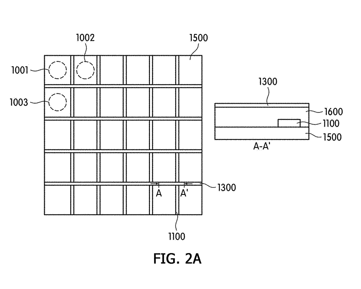
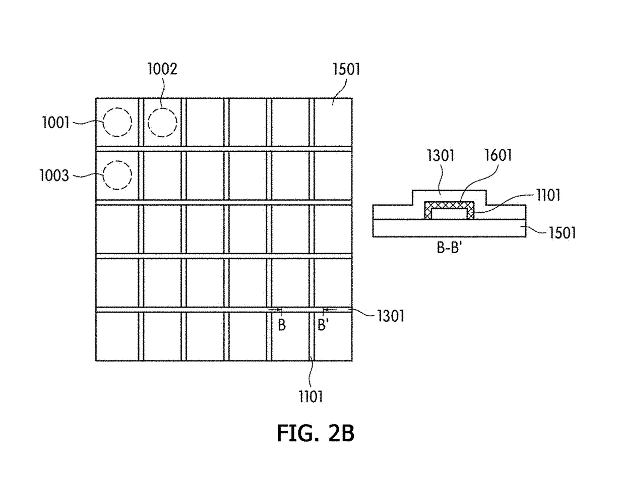
[0143]The electrode lines shown in FIGS. 2A, 3A, and 4A were formed on a base substrate formed of a quartz material and having a thickness of 800 μm. Here, in the electrode lines, the first mounting electrode had a width of 3 μm, the second mounting electrode had a width of 3 μm, a distance between the first mounting electrode and the second mounting electrode adjacent thereto was 2.2 μm, the mounting electrode had a thickness of 0.2 μm, materials of the first mounting electrode and the second mounting electrode were gold, and an area of a region in which the ultra-small LED devices were mounted on the mounting electrode line was 4.2×107 μm2. Then, an insulating layer made of silicon dioxide was formed in a separate space between lower portions of the mounting electrode lines on the base substrate. Then, an insulating partition wall made of silicon dioxide and surrounding the mounting electrode line was formed, and the insulating partition wall had a height of 0.1 μm from an upper p...

examples 2 and 3

[0148]Examples 2 and 3 were manufactured using the same method as Examples 1, and LED displays including an ultra-small LED electrode assembly shown in the following Table 2 were manufactured by self-aligning ultra-small LED devices by applying sine wave powers having voltages and cycles shown in the following Table 2, which were assembly powers applied to mounting electrodes, to the mounting electrodes.

experimental example 1

[0150]The following physical properties of one ultra-small LED electrode assembly provided in each of the LED displays manufactured as Examples 1 to 3 and Comparative Examples 1 to 3 were measured, and the results are shown in the following Table 2.

[0151]1. Measurement of the Total Number of Ultra-Small LED Devices Mounted in the Ultra-Small LED Electrode Assembly

[0152]A picture of the ultra-small LED electrode assembly was captured using an optical microscope, and the number of the ultra-small LED devices having both end portions in contact with different two electrodes was counted.

[0153]2. The Number and Percentage of the Ultra-Small LED Devices Mounted to have a Unidirectional Orientation

[0154]The number of the ultra-small LED devices which emitted light due to the ultra-small LED electrode assembly being driven with DC power having a waveform of +21.2 V without a cycle was counted to measure the number of the mounted ultra-small LED devices having the first semiconductor layer o...


PUM


Abstract

A full-color light emitting diode (LED) display having an improved luminance is provided herein. More specifically, provided herein are a full-color LED display, in which an amount of light blocked by electrodes and not extracted is minimized and ultra-small LED devices are connected to ultra-small electrodes without defects such as electrical short circuits and the like, wherein the full-color LED display exhibits a further improved luminance when a direct current (DC) driving voltage is used and each pixel of the full-color LED display exhibits uniform luminance when the DC driving voltage is used, and a method of manufacturing the same.

Description

BACKGROUNDField of the Invention[0001]The present invention relates to a full-color light emitting diode (LED) display, and more particularly, a full-color LED display in which an amount of light blocked by electrodes and not extracted is minimized and ultra-small LED devices are connected to ultra-small electrodes without defects such as electrical short circuits and the like, wherein the full-color LED display exhibits a much improved luminance when a direct current (DC) driving voltage is used, and each pixel of the full-color LED display exhibits uniform luminance when the DC driving voltage is used, and a method of manufacturing the same.Discussion of Related Art[0002]Light emitting diode (LED) devices have been actively developed since Nakamura of Nichia Co. in Japan succeeded in fusing a high-quality single crystalline GaN nitride semiconductor in 1992 by applying a low-temperature GaN compound buffer layer thereto. An LED is a semiconductor having a structure, in which an N-...

Claims


Application Information

Patent Timeline
IPC IPC(8): H01L27/32H01L33/38G09G3/32H01L33/50H01L27/15H01L33/44
CPCH01L27/3213H01L33/38H01L27/15H01L33/504G09G3/32H01L33/508G09G2310/0264G09G2300/0452H01L33/44H01L25/0753H01L33/62H10K59/351
Inventor DO, YOUNG RAGEO, YUN JAESUNG, YEON GOOG
Owner SAMSUNG DISPLAY CO LTD
Why Eureka
Eureka Blog
Learn More