Method for forming display part of push-type switch and push-type switch with the display part

A display and switch technology, applied in the direction of electric switches, legends, electrical components, etc., can solve the problems of image deformation, poor operation feeling of membrane switch, easy to generate burrs, etc., and achieve excellent moisture resistance and atmospheric corrosion resistance Excellent, excellent absorption effect

Inactive Publication Date: 2008-09-10
POLYMATECH CO LTD
View PDF6 Cites 0 Cited by
  • Summary
  • Abstract
  • Description
  • Claims
  • Application Information

AI Technical Summary

Problems solved by technology

[0007] However, such a method requires a process of cutting the exterior film 104 along the outer peripheral shape of each membrane switch with a carbon dioxide laser or a punching knife, and burrs are likely to be generated during cutting.
Furthermore, in such a method, it is generally necessary to provide a protective plate to protect the printing surface printed by the color printer. If it is included in the thickness of the substrate, it will become quite thick, so when integrating it as a part of the membrane switch , will affect the flexibility of the finger pressing operation part, which will make the operating feeling of the membrane switch worse. In addition, there will be problems such as the pressing operation cannot be reliably connected with the open-close connection of the switch, and it is not suitable for thin-walled membranes whose structural advantages are chip switch
On the other hand, in order to avoid this problem, if the printed surface side of the color printer is attached to the part where the appearance of the electronic device appears, since the design image can be recognized from the inside (the side opposite to the printed surface), there is also image distortion. , it is difficult to recognize images with good reproducibility and high image recognition

Method used


Image

  • Method for forming display part of push-type switch and push-type switch with the display part
  • Method for forming display part of push-type switch and push-type switch with the display part
  • Method for forming display part of push-type switch and push-type switch with the display part

Examples


Embodiment 1

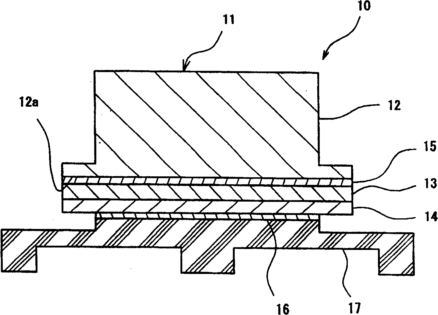
[0128] Embodiment 1: ( figure 1 ,figure 2)

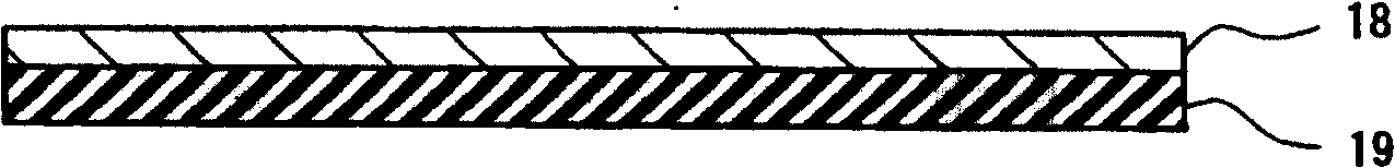
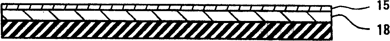
[0129] Color design data created using a computer is printed on a predetermined substrate 19 with a predetermined color printer, and the colored layer 18 is formed on the substrate 19 . On this substrate 19, a sample provided with a predetermined receiving layer (not shown in the figure) was prepared. On the inner surface 12a of the key top body 12 made of polycarbonate resin molded by an injection molding machine, or on the colored layer 18, the hot-melt adhesive 15 with a specified light transmittance of 5 μm is uniformly coated with a layer thickness of 5 μm by screen printing, And let it dry and solidify. Then, in order to transfer the colored layer 18 to the inner surface 12a of the key top body, the positions of the key top body 12 and the substrate 19 are aligned, and the key top body 12 and the substrate 19 are squeezed with a pressure of 0.3Mpa. After 2 seconds, add After performing thermal transfer at a predetermined t...

Embodiment 2

[0135] Embodiment 2: ( image 3 ,Figure 4)

[0136] Color design data created with a computer is printed on a predetermined substrate 29 using a predetermined color printer, and a colored layer 28 is formed on the substrate 29 provided with a predetermined receiving layer (not shown). On the surface 22a of the key top body 22 made of polycarbonate resin formed by an injection molding machine, a predetermined coloring auxiliary layer 24 was applied to a thickness of 5 μm according to a sample. Then, the hot-melt adhesive 25 having predetermined translucency is uniformly applied on the colored layer 28 or the surface 22a of the key top body 22 by screen printing, and dried and cured. In order to transfer the colored layer 28 on the key top body 22 side, align the positions of the key top body 22 and the substrate 29, press the key top body 22 and the substrate 29 with a pressure of 0.3Mpa, and add a specified temperature after 2 seconds. After thermal transfer, the substrate 2...

Embodiment 5

[0144] Embodiment 5: (Fig. 10)

[0145] The color design data created using a computer is printed with a printer on a substrate 58 made of a PET film or acrylic film with a thickness of 100 μm provided with a predetermined image bearing layer, and a colored layer 59 is formed on the substrate 58 . A hot-melt adhesive 53 with predetermined translucency is uniformly applied on the colored layer 59 by screen printing, and dried and solidified to a layer thickness of 5 µm. Moreover, cooperate with the prescribed light-transmitting film 53 with a thickness of 50 μm, transfer the colored layer 59 to the light-transmitting film 53 for position alignment, press the substrate 58 and the light-transmitting film 53 with a pressure of 0.3 Mpa, and pass through 2 seconds After thermal transfer at 200° C., the substrate 58 was peeled off, and the display layer 55 was formed on the surface of the light-transmitting film 53 . For each sample, a predetermined coloring auxiliary layer 56 was c...


PUM


Abstract

A method for forming an indicator portion on a push switch such as a pushbutton switch or a membrane switch, the indicator portion being excellent in terms of design property and image quality and allowing fine picture patterns, designs, etc. that are difficult to be reproduced with conventional printing systems to be represented with high resolution, and to provide a push switch having the indicator portion. In order to form the indicator portion, in which a color design image such as a letter, a pattern, design etc is indicated, on the push switch, there are performed the following steps of: forming a colorant layer by printing a color design image on a base sheet by a printer; transferring the colorant layer to a transfer resin through an adhesive, the transfer resin constituting a surface of the push switch; and forming the indicator layer on the transfer resin by peeling off the base sheet and using the colorant layer as the indicator layer.

Description

technical field [0001] The present invention relates to a push switch such as a membrane switch used as a thin switch input device in electronic equipment, mobile equipment, vehicle switches, push switches used in operating parts of remote controllers, etc., electronic equipment, etc.; Specifically, the present invention relates to a method of forming a display portion of a color design image representing characters, patterns, patterns, etc. on a push button switch and a push button switch having the display portion. A method for forming a display portion of a color design image in a membrane switch and a membrane switch having the display portion. Background technique [0002] Push button switches used in electronic equipment such as mobile phones have a display layer for displaying color images such as letters, numerals, figures, symbols, and designs. The display layer is mainly formed by printing characters, symbols, and other shapes on resin key tops by screen printing,...

Claims


Application Information

Patent Timeline
Patent Type & Authority Patents(China)
IPC IPC(8): H01H11/00H01H13/14H01H13/702
CPCH01H2229/006H01H2219/028H01H13/702H01H2229/01H01H2219/034
Inventor 新井宏本松良文
Owner POLYMATECH CO LTD
Why Eureka
Try Eureka