
Radial shaft seal assembly with axially adaptive debris exclusion face lip and oil seal face lip

a technology of radial shaft seals and oil seals, applied in the direction of engine seals, mechanical devices, engine components, etc., can solve the problems of excessive friction, drag, wear, etc., and achieve the effect of reducing drag and friction, and reducing the chance of contamination ingress

Inactive Publication Date: 2019-03-26
TENNECO INC
View PDF23 Cites 5 Cited by
  • Summary
  • Abstract
  • Description
  • Claims
  • Application Information

AI Technical Summary

Benefits of technology

The assembly provides a robust, low-friction, and long-lasting seal that remains effective even with axial misalignment, offering a compact and economical solution with reduced contamination ingress and prolonged life expectancy.

Problems solved by technology

Otherwise, if the outer seal component is axially misaligned with the inner seal component, one of the main oil seal lip and dust exclusion lip will be brought into excessive interference with its respective sealing surface, thereby resulting in excessive friction, drag, and wear.

Method used


Image

  • Radial shaft seal assembly with axially adaptive debris exclusion face lip and oil seal face lip
  • Radial shaft seal assembly with axially adaptive debris exclusion face lip and oil seal face lip
  • Radial shaft seal assembly with axially adaptive debris exclusion face lip and oil seal face lip

Examples


Embodiment Construction

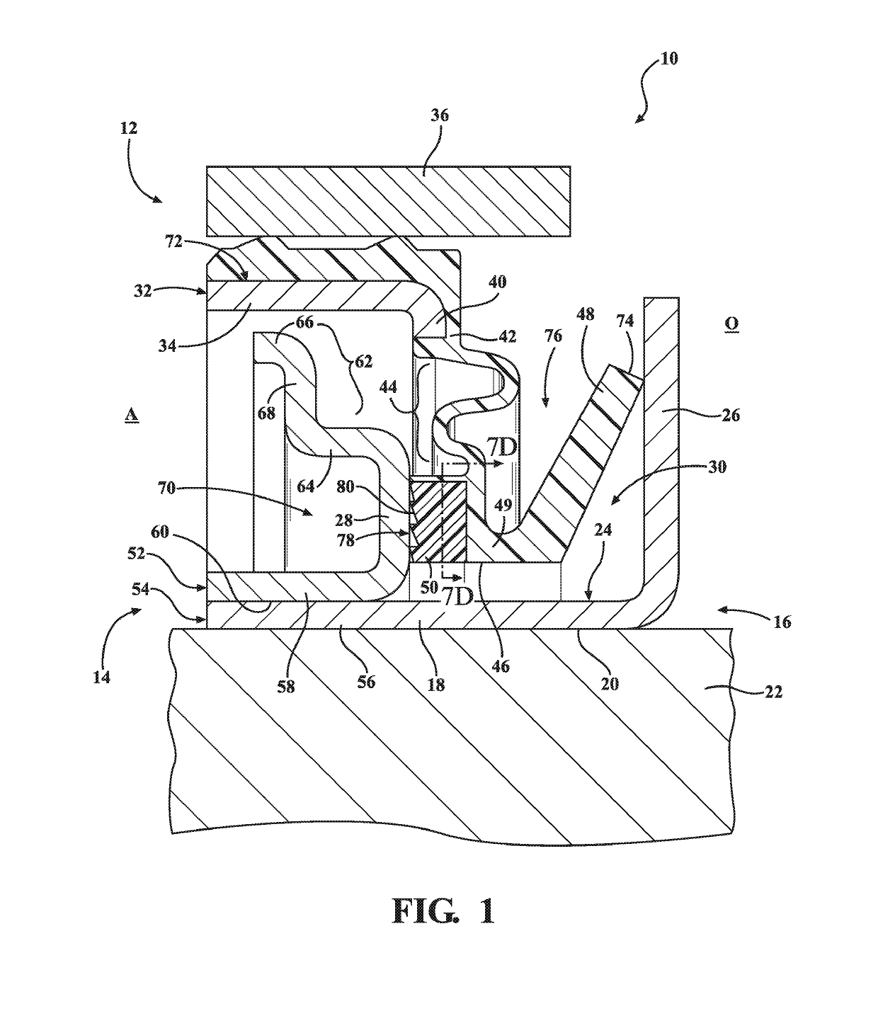
[0036]Referring in more detail to the drawings, FIG. 1 illustrates a dynamic radial shaft seal assembly, referred to hereafter as assembly 10, constructed in accordance with one aspect of the invention. The assembly 10 maintains lubricant, e.g. oil, on an oil side O of the assembly, thereby inhibiting the egress of lubricant outwardly from the assembly 10, while preventing dust and other forms of contamination on an air side A of the assembly from entering the oil side O, thereby inhibiting the ingress of contamination into the assembly 10. The assembly 10 includes an annular outer seal component 12 and an annular inner seal component 14. The inner seal component 14 includes an inner wear sleeve 16 having a cylindrical wall 18 including a bore 20 sized for close receipt about a shaft 22 and an exposed cylindrical outer surface 24. Further, the wear sleeve 16 has an oil side flange 26 and an air side flange 28 extending radially outwardly from the cylindrical inner wall 18 in axially...


PUM


Abstract

A radial shaft seal assembly is provided including an inner wear sleeve having a cylindrical wall with a bore sized for tight receipt of a shaft therethrough and an exposed cylindrical outer surface. The inner wear sleeve includes an oil side flange and an air side flange extending radially outwardly from the inner wall in axially spaced relation from one another. The assembly includes an outer case having cylindrical outer wall configured for receipt in a housing. An elastomeric body is fixed to the outer case. The elastomeric body includes an annular serpentine portion extending radially inwardly from the outer wall to a radially innermost end. A main seal lip extends from the innermost end of the annular serpentine portion into sealed contact with the oil side flange. A dust lip extends from the innermost end of the annular serpentine portion into sealed contact with the air side flange.

Description

BACKGROUND OF THE INVENTION1. Technical Field[0001]This invention relates generally to dynamic radial shaft seals, and more particularly to a dynamic radial shaft seal having axially oppositely facing dust exclusion and oil seal face lips.2. Related Art[0002]Dynamic radial shaft face seals are known to include an annular outer seal component and an annular inner seal component. The outer seal component is configured to be mounted in a housing about an opening to be sealed and the inner seal component, including a wear sleeve, is configured to be mounted on a shaft extending through the opening for co-rotation therewith. The outer seal component typically includes an outer metal case having a metal cylindrical portion sized for press fit into the housing with a leg extending radially inwardly from the cylindrical portion. Further, an elastomeric body is typically attached to the leg, with a main oil seal lip extending radially inwardly into sealed abutment with the wear sleeve. Furth...

Claims


Application Information

Patent Timeline
Patent Type & Authority Patents(United States)
IPC IPC(8): F16J15/32F16J15/3256F16J15/3284F16J15/3224F16J15/3232
CPCF16J15/3232F16J15/3284F16J15/3256F16J15/3224F16J15/3456
Inventor TOTH, DAVID M.
Owner TENNECO INC
Learn More