Doppler ultrasonic velocity probe

a technology of ultrasonic velocity and probe, which is applied in the field of vibration monitoring systems, can solve the problems of eddy-current proximity displacement probe and spring-coil velocity transducer, affecting the effectiveness of vibration monitoring sensors for large rotating machinery, and affecting the accuracy of vibration monitoring, so as to eliminate any potential for transmission noise and eliminate background noise

Active Publication Date: 2019-03-26
LOVEJOY CONTROLS
View PDF27 Cites 0 Cited by
  • Summary
  • Abstract
  • Description
  • Claims
  • Application Information

AI Technical Summary

Benefits of technology

[0004]The probe analyzer circuit may include, among others, lowpass filters, scale amplifiers, and a primary component selective Phase Locked Loop Demodulator (PLLD) to eliminate background noise from the signal detected by the ultrasonic microphone. Within the probe analyzer circuit, a microcomputer performs analog to digital conversion of the signal, generates vibration analysis data from the signal, and generates probe health diagnostics of the probe. In addition, the microcomputer preferably contains a serial communications network that is buffered with a transceiver chip and is hard wired by way of an RS-485 connection to an LCCNET proprietary device which provides data polling of a network of probes as a host on a query / response basis. The LCCNET device is then hard wired by way of a RS-232 USB cable to a data display and distribution computer that is equipped with software to provide graphical data displays, diagnostics, alarms, and a preferably an Ethernet link to an external server.
[0005]A separate means for vibration analysis is not required since the present system performs all vibration analysis required to detect vibration phenomena, and transmits said vibration analysis to a host computer all in one system. Additionally, by performing the vibration analysis and signal processing within the same system as the probe sensor, any potential for transmission noise is eliminated.
[0007]As will be discussed, a system according to the present invention further preferably includes a temperature and humidly compensation sensor and an extension tube support, with all components positioned at a fixed distance from a target rotating shaft. The temperature and relative humidity sensor detects and signals the system to compensate for variations in the ambient temperature and relative humidity of the test application. The ambient temperature and relative humidity of the application, for example a turbine monitoring atmosphere, affects the speed of sound by up to 25%. Such changes in the speed of sound directly impact the Doppler velocity. The microcomputer receives temperature and humidity senor data through a Serial Peripheral Interface (SPI) port and digitally applies the temperature and relative humidity corrections directly to the analog to digital conversion in software. This arrangement provides for highly accurate gain corrections to the signal from changes in temperature and relative humidity, keeping the sensor system in acceptable calibration at all times. The present design preferably utilizes a 25.000 KHz (+ / −200 Hz) incidence wave frequency.

Problems solved by technology

Known vibration monitoring sensors for large rotating machinery, eddy-current proximity displacement probes and spring-coil velocity transducers, are hampered with intrinsic errors lessening their effectiveness in providing diagnostic warning or data for balancing and accurate rotor deflection monitoring to determine approaching internal contact between rotating and stationary elements thus protecting against rotor damage during start ups.
For example, eddy-current proximity displacement probes may suffer from electrical run-out, magnetic run-out, surface irregularity (dents, scratches, grooves) spiking, and ill-defined calibration.
Spring-coil velocity transducers suffer poor low speed outputs, mechanical resonance, and difficulty with coupling to a rotating shaft without use of a contacting shaft rider which itself is spiked by surface irregularities.

Method used


Image

  • Doppler ultrasonic velocity probe
  • Doppler ultrasonic velocity probe
  • Doppler ultrasonic velocity probe

Examples


Embodiment Construction

[0017]Although the disclosure hereof is detailed and exact to enable those skilled in the art to practice the invention, the physical embodiments herein disclosed merely exemplify the invention which may be embodied in other specific structures. While the preferred embodiment has been described, the details may be changed without departing from the invention, which is defined by the claims.

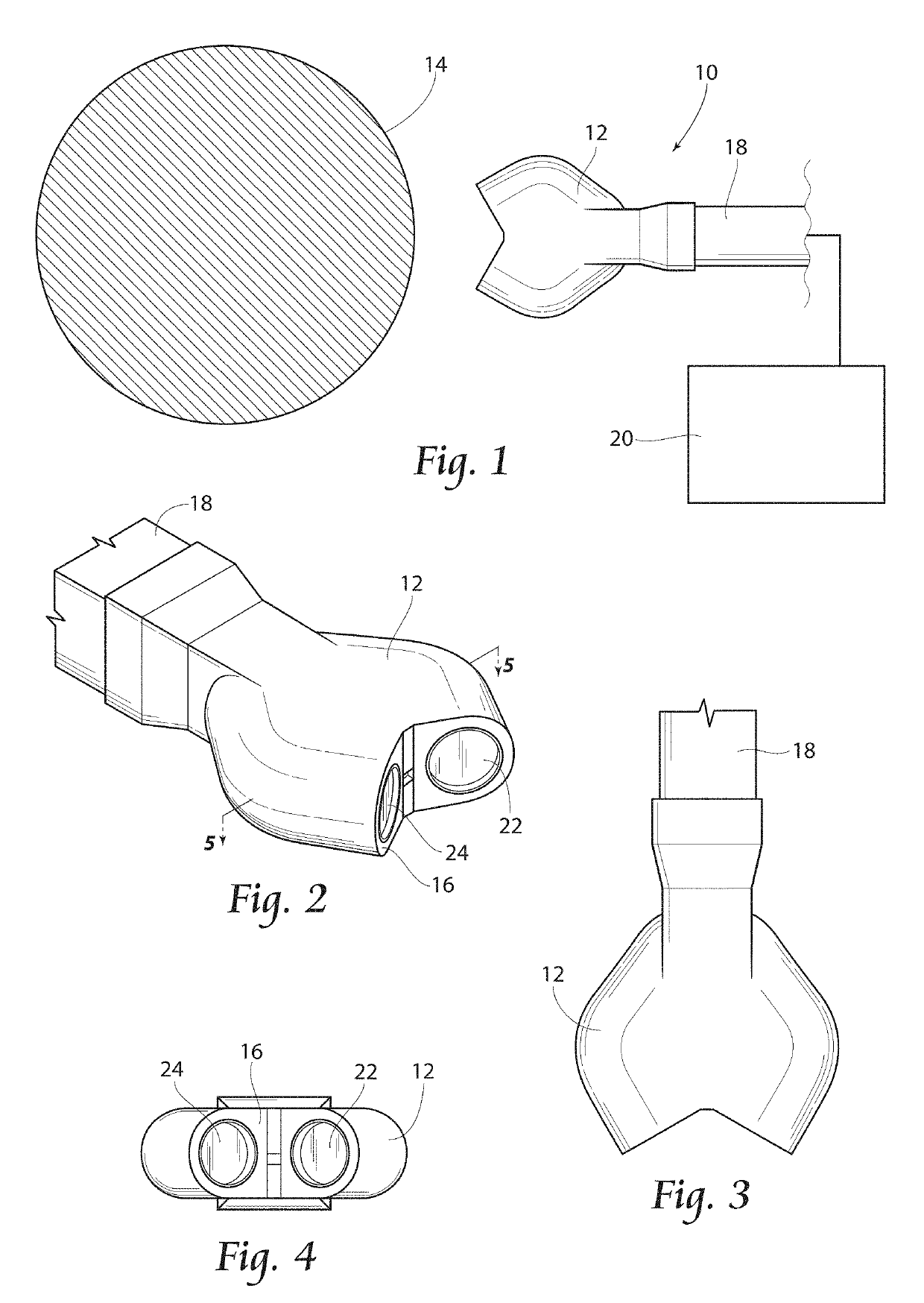
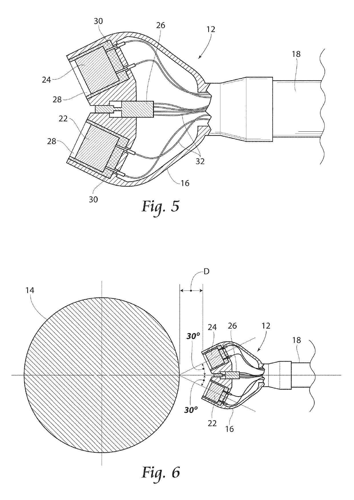
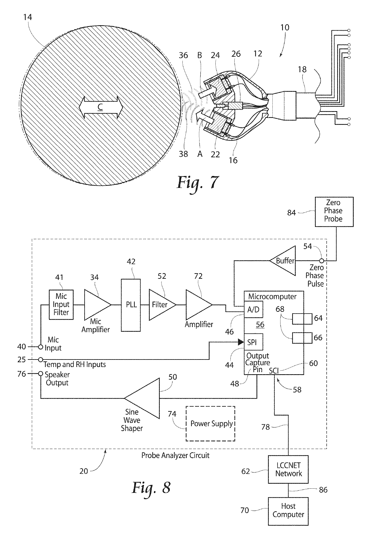
[0018]With reference to FIGS. 1 and 2, a system 10 having a probe sensor 12 according to the present invention may he seen. As shown, the system 10 provides a device and method adapted to measure the vibrations of a test object 14, such as a machine shaft or other rotating object. The system 10 includes a probe sensor 12 having a housing 16, an extension tube support 18, and a probe analyzer circuit 20. As seen in FIG. 2, a probe sensor 12 for use with the present system. 10 preferably includes an ultrasonic speaker 22 and an ultrasonic microphone 24. The probe sensor 12 may further include a temp...


PUM


Abstract

A system and method for measuring the vibrations of a test object, such as a machine shaft or other rotating equipment. The system includes a probe sensor fitting having an ultrasonic speaker and an ultrasonic microphone. The probe sensor fitting includes a temperature and relative humidity sensor. The system further includes a probe analyzer circuit with a microcomputer that generates vibration analysis data and probe health diagnostics.

Description

RELATED APPLICATIONS[0001]This application is a continuation-in-part of co-pending U.S. patent application Ser. No. 14 / 819,131, filed 5 Aug. 2015.BACKGROUND OF THE INVENTION[0002]The present invention is directed to vibration monitoring systems, particularly systems for use with large rotating machinery. Known vibration monitoring sensors for large rotating machinery, eddy-current proximity displacement probes and spring-coil velocity transducers, are hampered with intrinsic errors lessening their effectiveness in providing diagnostic warning or data for balancing and accurate rotor deflection monitoring to determine approaching internal contact between rotating and stationary elements thus protecting against rotor damage during start ups. For example, eddy-current proximity displacement probes may suffer from electrical run-out, magnetic run-out, surface irregularity (dents, scratches, grooves) spiking, and ill-defined calibration. Spring-coil velocity transducers suffer poor low s...

Claims


Application Information

Patent Timeline
Patent Type & Authority Patents(United States)
IPC IPC(8): G01H17/00G01S15/58
CPCG01S15/586G01H17/00G01H9/008G01S7/52006G01S7/521
Inventor LOVEJOY, KIM A.
Owner LOVEJOY CONTROLS
Why Eureka
Try Eureka