Method for removing background noise in shear wave and corresponding ultrasonic imaging system

An ultrasonic imaging system, background noise technology, applied in radio wave measurement system, ultrasonic/sonic wave/infrasonic wave diagnosis, application, etc., can solve the problem of increasing the sound output power, achieve the effect of reducing duration and voltage, and eliminating background noise

Active Publication Date: 2014-07-09
GE MEDICAL SYST GLOBAL TECH CO LLC
View PDF4 Cites 13 Cited by
  • Summary
  • Abstract
  • Description
  • Claims
  • Application Information

AI Technical Summary

Problems solved by technology

This will significantly increase the acoustic output power, even beyond FDA (Food and Drug Administration) limits

Method used


Image

  • Method for removing background noise in shear wave and corresponding ultrasonic imaging system
  • Method for removing background noise in shear wave and corresponding ultrasonic imaging system
  • Method for removing background noise in shear wave and corresponding ultrasonic imaging system

Examples


Embodiment Construction

[0017] The present invention will be further described below in conjunction with the accompanying drawings and specific embodiments.

[0018] The following include definitions of selected terms used herein. These definitions include various examples and / or forms of components that fall within the scope of the terms and can be used for implementation. Examples are not intended to be limiting. These definitions may include both singular and plural forms of terms.

[0019] References to "one embodiment," "an embodiment," "an example," "example," etc. indicate that such described embodiments or examples may include a particular feature, structure, characteristic, property, element, or limitation, but not every Each embodiment or example necessarily includes specific features, structures, characteristics, properties, elements or limitations. Additionally, repeated use of the phrase "in one embodiment" does not necessarily refer to the same embodiment, although it may.

[0020] ...


PUM


Abstract

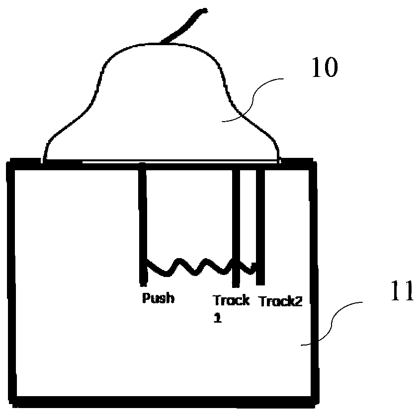
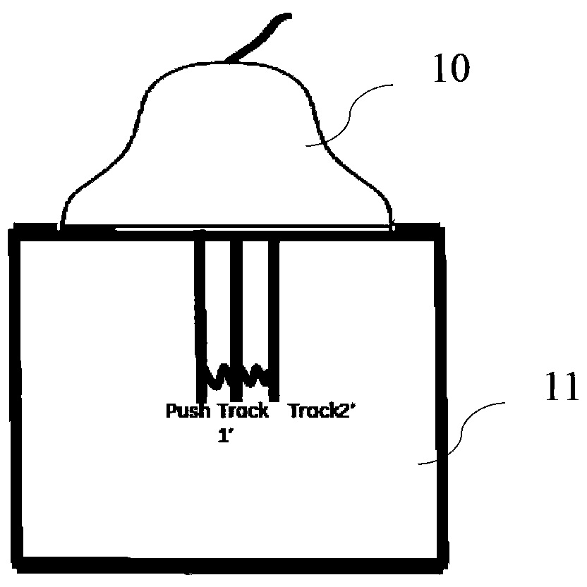
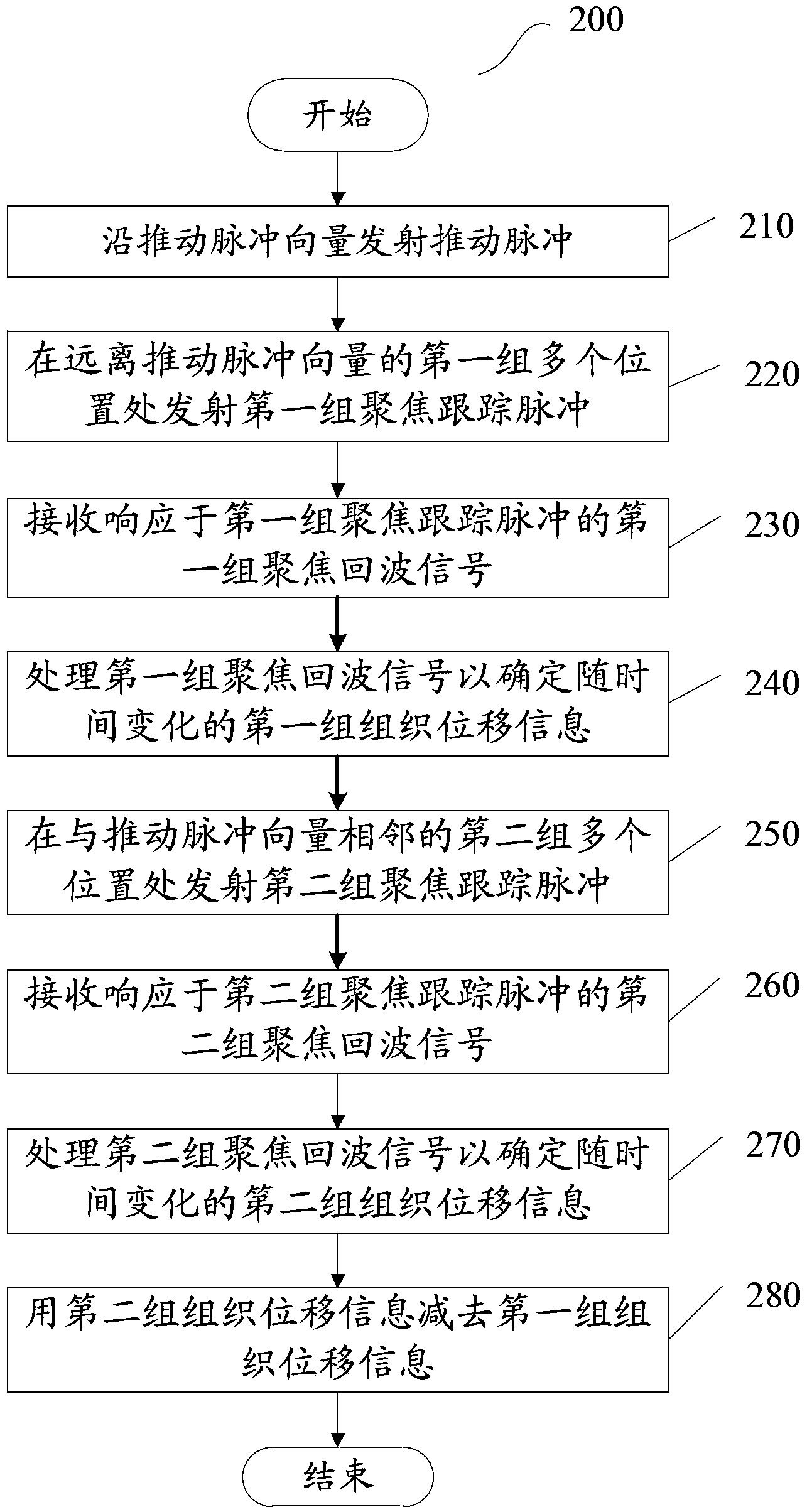
A method for eliminating background noises in shear waves and the respective ultrasonic imaging system, the method includes: transmitting a push pulse along a push pulse vector; transmitting a first group of focus track pulses at a first group of a plurality of locations far away from the push pulse vector; receiving a first group of focus echo signals in response to the first group of focus track pulses; and processing the first group of focus echo signals to determine a first group of tissue displacement information varying with time.

Description

technical field [0001] The present invention generally relates to the field of ultrasonic testing, and more particularly to a method, device and ultrasonic imaging system including the device for eliminating background noise in shear waves. Background technique [0002] Ultrasonic testing is a commonly used testing method in the modern medical field. [0003] When sound waves propagate in a heterogeneous medium, an acoustic pulse radiation force (Acoustic radiation force) is generated. Acoustic pulse radiation forces can characterize the biomechanical elasticity of tissues. This has sparked research interest in the fields of materials science and medical diagnostics. [0004] One of the long-sought goals of diagnostic imaging is the accurate characterization of tissue. A clinician wants to obtain a diagnostic region of a body organ and have the imaging system identify features of the tissue in the image. Ideally, clinicians would like the imaging system to identify wheth...

Claims


Application Information

Patent Timeline
Patent Type & Authority Applications(China)
IPC IPC(8): A61B8/00
CPCA61B8/14A61B8/485A61B8/5276G01S7/52077G01S7/52036G01S7/52042
Inventor 唐露程刚韩晓东沈亮
Owner GE MEDICAL SYST GLOBAL TECH CO LLC
Why Eureka
Try Eureka