
Slot antenna device

a technology of antenna device and slot antenna, which is applied in the structure of radiating elements, static indicating devices, instruments, etc., can solve the problems of complicated design of slot antenna structure capable of being operated at multiple frequency bands, and achieve the effect of reducing the complexity of the slot structur

Active Publication Date: 2019-03-26
E INK HLDG INC
View PDF30 Cites 0 Cited by
  • Summary
  • Abstract
  • Description
  • Claims
  • Application Information

AI Technical Summary

Benefits of technology

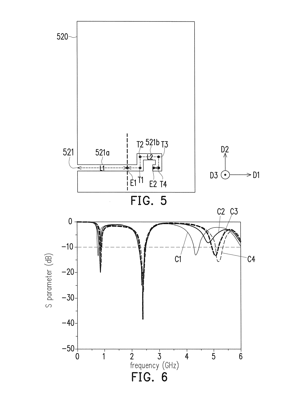
Enables efficient operation across multiple wireless charging frequency bands, such as 915 MHz, 2.45 GHz, and 5.25 GHz, with reduced structural complexity and cost, while maintaining effective impedance matching and frequency bandwidth properties.

Problems solved by technology

Therefore, if the slot antennae could be operated at multiple charging frequency bands, a multiple-slots structure has to be designed to emit the other frequency bands, thus designing the slot antenna structures that are capable of being operated at multiple frequency bands becomes complicate.

Method used


Image

  • Slot antenna device
  • Slot antenna device
  • Slot antenna device

Examples


Embodiment Construction

[0037]Reference will now be made in detail to the present preferred embodiments of the invention, examples of which are illustrated in the accompanying drawings. Wherever possible, the same reference numbers are used in the drawings and the description to refer to the same or like parts.

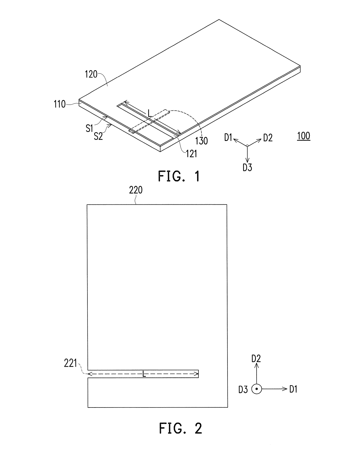
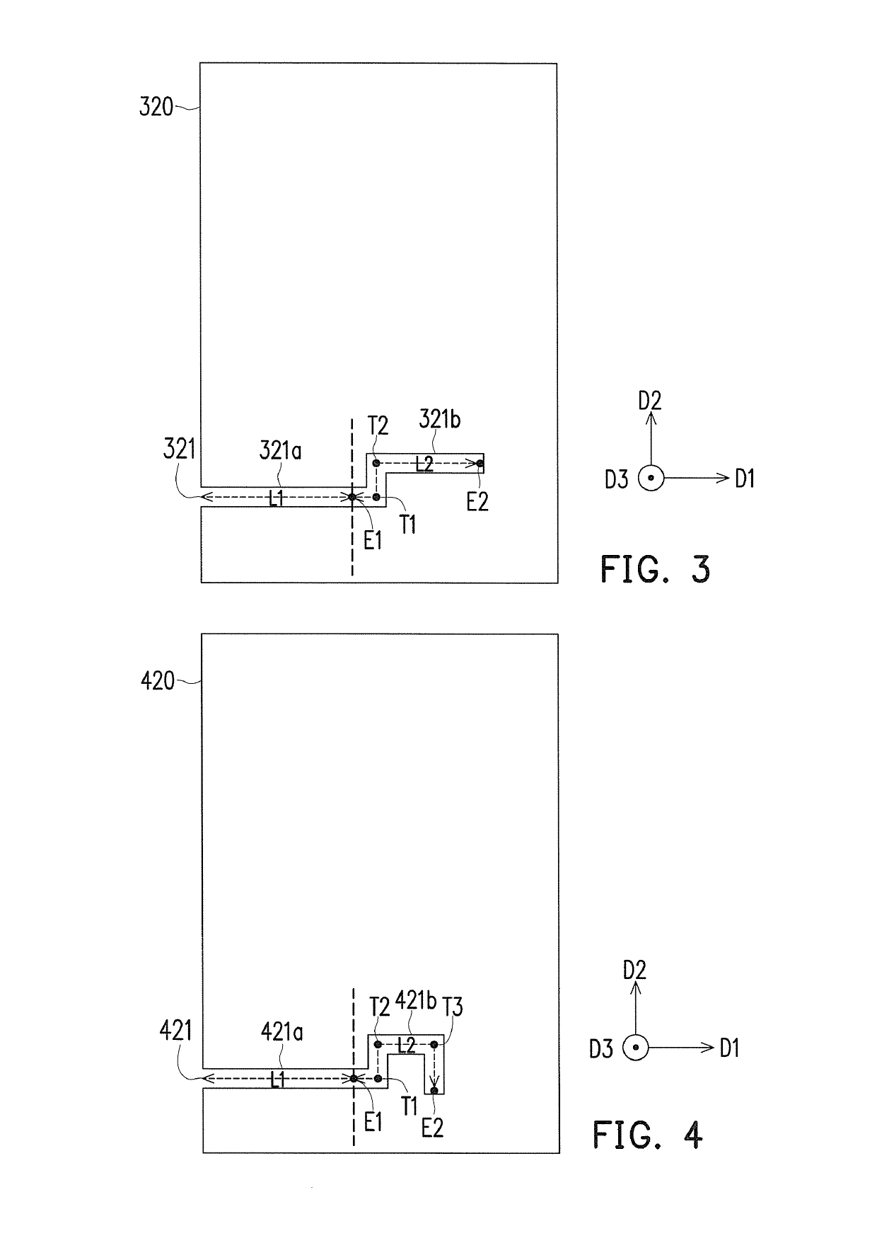
[0038]Multiple embodiments are provided to describe the present invention. However, the present invention should not be limited to these exemplary embodiments. In addition, appropriate combination of the embodiments is also available. Furthermore, in the specification (including the claims) of the present application, antenna devices in embodiments of the present invention may be regarded as being located in a space constructed by a first direction D1, a second direction D2 and a third direction D3, to elaborate locations of slots and feeding elements in the antenna devices of the embodiments of the present invention. The first direction D1 is, for example, substantially perpendicular to the second d...


PUM


Abstract

A slot antenna device including a substrate, a metal layer and a feeding element is provided. The substrate has a first surface and a second surface opposite to the first surface. The metal layer is disposed on the first surface, and includes a slot extending along a first direction. The feeding element is disposed on the second surface, and extended along a second direction, where the first direction is perpendicular to the second direction. A length of the slot is a sum of each quarter wavelength of at least three frequency bands, so that the slot antenna device is operated at the at least three frequency bands. A projection of the feeding element on the first surface crosses the slot, so that the slot is divided into a first section and a second section, where a length of the first section is equal to a length of the second section.

Description

CROSS-REFERENCE TO RELATED APPLICATION[0001]This application claims the priority benefits of U.S. provisional application Ser. No. 62 / 296,601 filed on Feb. 18, 2016 and China application serial no. 201610849318.6, filed on Sep. 26, 2016. The entirety of each of the above-mentioned patent applications is hereby incorporated by reference herein and made a part of this specification.BACKGROUND OF THE INVENTION[0002]1. Field of the Invention[0003]The present invention generally relates to an antenna device, in particular, to a slot antenna device.[0004]2. Description of Related Art[0005]As the development of wireless charging technology, there have been increasing numbers of portable electronic devices disposed with charging antennae to receive charging signals via a wireless transmission manner, so that the portable electronic devices have a function of wireless charging. Specifically, most of the current charging antennae are designed by adopting a slot antenna structure. However, gen...

Claims


Application Information

Patent Timeline
Patent Type & Authority Patents(United States)
IPC IPC(8): H01Q13/10H01Q1/24H01Q1/36H01Q5/30H01Q1/22H01Q5/357
CPCH01Q13/106H01Q1/2291H01Q1/243H01Q13/10H01Q5/30H01Q5/357H01Q1/36H01Q1/38H01Q1/50H01Q5/00G09G3/344
Inventor LEE, YU-MING
Owner E INK HLDG INC
Learn More