Solar module

a solar module and solar panel technology, applied in the field of solar modules, can solve the problems of increasing the susceptibility to wind, affecting the flexibility of solar panels, and damage to solar panels, and achieve the effect of reducing friction and simplifying mounting

Active Publication Date: 2019-03-26
SFS ACQUISITION LLC
View PDF12 Cites 0 Cited by
  • Summary
  • Abstract
  • Description
  • Claims
  • Application Information

AI Technical Summary

Benefits of technology

[0017]Preferably, for reducing friction, the end sections are mounted via a common sliding sleeve on the axis, which simplifies mounting. Furthermore, sliding disks can be a...

Problems solved by technology

The invention is based on the findings that dragging strips, which run across the whole length of the solar panels, lead to a disadvantageous entanglement of the solar panels in the fanned-out state, which impairs their flexibility and thereby increases their susceptibility to wind; the dragging strips can furthermore lead to damages of the solar panels caused by v...

Method used


Image

  • Solar module
  • Solar module
  • Solar module

Examples


first embodiment

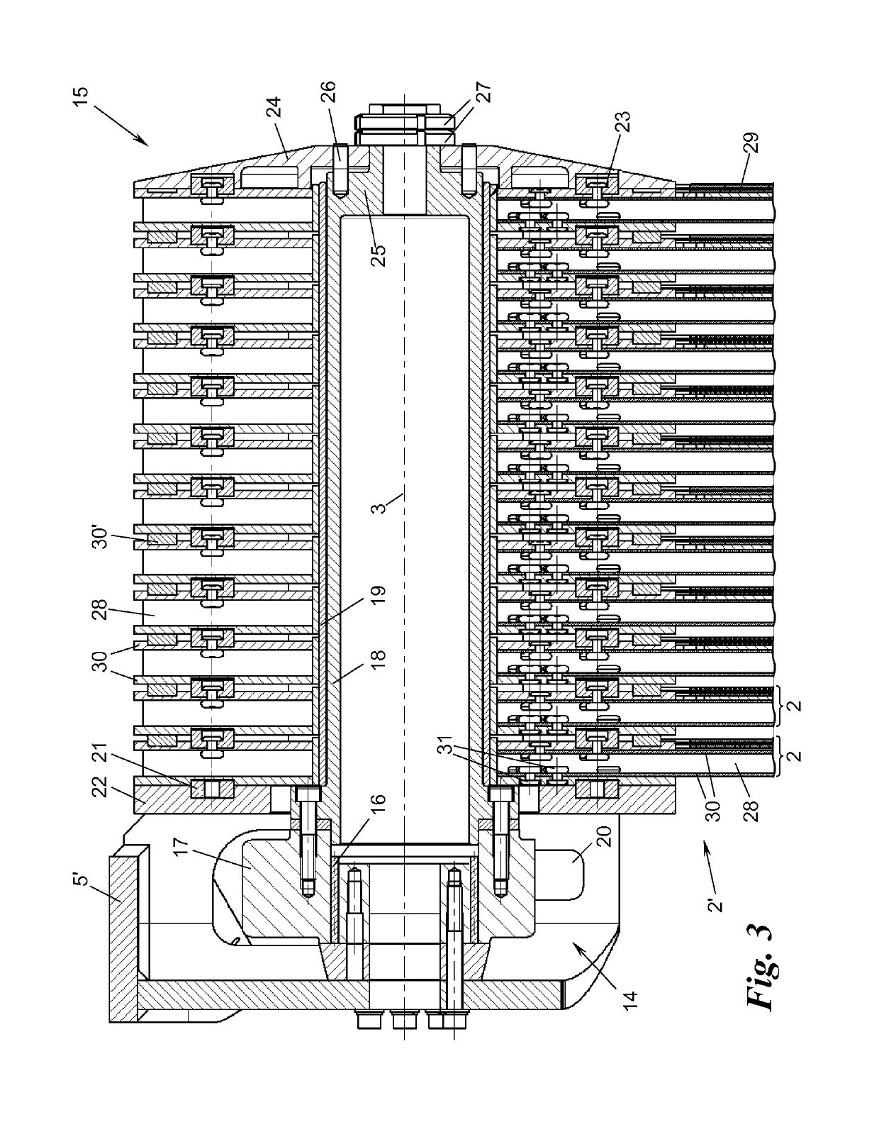
[0032]FIG. 3 shows the fanning-out mounting 15 for pivotingly mounting the radially inner end sections 2′, which lie on the side of the axis, of the solar panels 2 on an end piece 5′ of the swivel head 5 in a sectional view. The head end piece 5′ mounts a tubular axis 18 via a rolling bearing 16 and an anchoring ring 17, onto which axis 18 the end sections 2′ of the solar panels 2—if applicable by interposing a sliding sleeve 19, e.g., made out of plastic such as, for example, PTFE—are threaded and mounted pivotingly. The end sections 2′ simultaneously serve for a dragging drive of the solar panels 2 during fanning-out and fanning-in. For this purpose, the axis 18 is rotationally driven about the rotation axis 3 by the rotation drive 14. The rotation drive 14 can, for example, be realised by providing the bearing ring 17 with an outer toothed ring and driving it via a worm drive 20 (depicted only schematically). The axis 18 could, however, also be rotationally driven in another way ...

second embodiment

[0037]FIGS. 5, 6a, and 6b show the solar panels 2, their end sections 2′, and the fanning-out mounting 15. In this embodiment, each end section 2′ has only one mounting plate 38, on which the support struts 28 are mounted on one side, for example, via screw joints 39. The mounting plates 38 are, for example, made out of 8 mm thick aluminium. Since the support struts 28 and the photovoltaic panels 29 carried by them have a higher thickness and the mounting plates 38 are thus to be mounted in an accordingly distanced manner on the axis 18, each mounting plate 38 is here provided with a spacer disk 40 lying against it on one side.

[0038]The spacer disk 40 is, for example, a plastic injection-moulded piece and contains—along further through-holes 41 for reducing material and weight—tangential oblong holes 35 analogue to the first embodiment of FIGS. 3 and 4. Again, bolts 42 engage into the oblong holes 35, which bolts 42 are anchored to the mounting plate 38 of the respective neighbourin...

third embodiment

[0041]FIGS. 7 and 8 show the solar panels 2, their end sections 2′, and the fanning-out mounting 15. Each end section 2′ here again comprises one single mounting plate 38, as in the embodiment of FIGS. 5 and 6, on which the support struts 28 for the photovoltaic module 29 are mounted via screwed or riveted joints 39. Between the mounting plates 38 of two neighbouring end sections 2′, there is again provided a spacer disk 45. The spacer disks 45 are this time, however, not connected with each respective flange plate 38 in a rotation-fixed manner, but are embodied in form of loose sliding disks, which rest on the axis 18, wherein the sliding disks are provided on at least one side with a slide coating or a separate sliding ring 45′ or are generally made out of friction-reducing material, like for example PTFE-plastic.

[0042]The spacer disks 45 have tangential oblong holes 46 or even bigger through holes, which now do not form limiting stops for catches themselves (as in the previous em...


PUM


Abstract

Disclosed is a solar module, comprising a plurality of lamellar solar panels, which are mounted on a common axis so as to be able to pivot between a first position, in which they are positioned one on top of the other in a substantially coincident manner, and a second position, in which they are fanned out substantially adjacently, wherein, of every two adjacent solar panels, only the axis-side end section of the one solar panel has at least one guide and only the axis-side end section of the other solar panel has two stops which interact with the guide and are spaced from each other in the tangential direction, and wherein the solar panels are spaced from each other in the fanned out second position in their radially projecting sections that adjoin the aforementioned end sections.

Description

CROSS-REFERENCE TO RELATED APPLICATIONS[0001]This application is a National Phase application of International Application No. PCT / AT2014 / 050019 filed Jan. 20, 2014 which claims priority to Austrian Patent Application No. A 50050 / 2013 filed Jan. 23, 2013, the disclosures of which are incorporated herein by reference.FIELD OF THE INVENTION[0002]The present invention relates to a solar module, comprising a plurality of lamellar solar panels, which are mounted on a common axis so as to be able to pivot between a first position, in which they are positioned one over the other in a substantially congruent manner, and a second position, in which they are fanned-out so as to substantially lie next to each other.BACKGROUND[0003]Such a solar module is known from document AT 509 886 B1 and has the advantage that the sensitive solar panels can be accommodated in a space-saving manner in the folded first position in a protective housing, in which they are protected from damages during the night...

Claims


Application Information

Patent Timeline
IPC IPC(8): H02S30/20
CPCH02S30/20A45B27/00Y02E10/50
Inventor SWATEK, ALEXANDERSTOGER, ELMARKASER, ALFREDPRASENT, MANFRED
Owner SFS ACQUISITION LLC
Why Eureka
Try Eureka