Rod tensioning device and assembly process of such a device on a rod

a technology of tensioning device and tensioning rod, which is applied in the direction of metal-working equipment, metal-working equipment, manufacturing tools, etc., can solve the problems that the tensioning device cannot be installed in places of reduced axial dimensions, and the tensioning device may not be suitable for use in a reduced space, so as to achieve the effect of reducing axial space and convenient installation

Active Publication Date: 2019-04-02
AB SKF
View PDF3 Cites 0 Cited by
  • Summary
  • Abstract
  • Description
  • Claims
  • Application Information

AI Technical Summary

Benefits of technology

[0008]The present invention seeks to provide an axially compact improved rod tensioning device allowing an easier installation in particular in places of reduced axial space.
[0013]Furthermore, these separate elements do not need to be fastened each other. The hydraulic pressure exerted by the pressurized fluid within the annular chambers of the actuators is enough to ensure the axial tightening of these elements together and onto the support structure.
[0014]Another advantage is that at least a second annular chamber on which the pressurized fluid acts is defined with the at least second actuator. Such a tensioning device integrating at least two annular chambers can be provided with the same pressure surface as a standard tensioning device with one unique annular chamber. A tensioning device can then be dimensioned with a reduced radial dimension but adapted to exert a similar tensioning force.
[0015]Another advantage is that the elements of the tensioning devices are temporary assembled and can be dismounted and mounted as many times as needed. The sealing means between the piston and the cylinder of each actuator is easily accessible after each dismounting and can be then easily checked and replaced after each device use.

Problems solved by technology

However, such tensioning device may not be suitable for use in a reduced space for mechanical structures requiring an important tensioning axial force.
Moreover, the rod tensioning device as known cannot be installed in places of reduced axial dimensions, in particular between a first structure from which axially protrude a rod and a second structure that is axially close to the free end of the protruding rod.

Method used


Image

  • Rod tensioning device and assembly process of such a device on a rod
  • Rod tensioning device and assembly process of such a device on a rod
  • Rod tensioning device and assembly process of such a device on a rod

Examples


Embodiment Construction

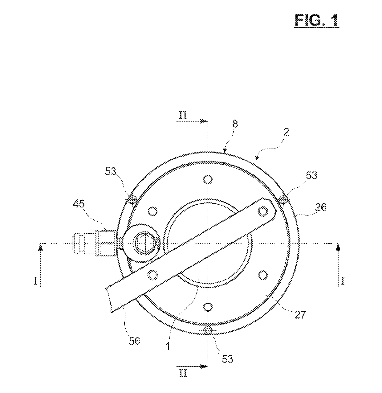
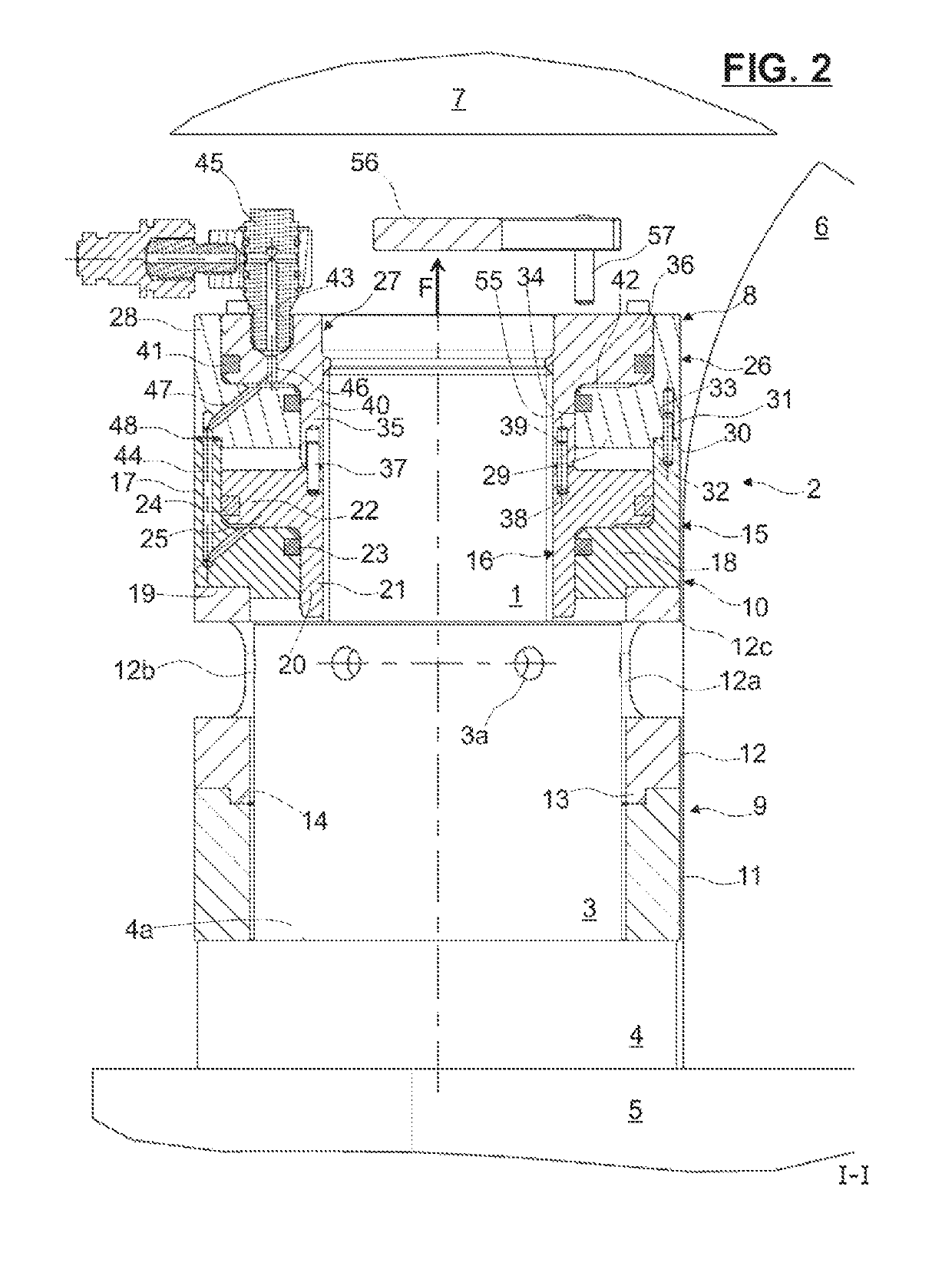
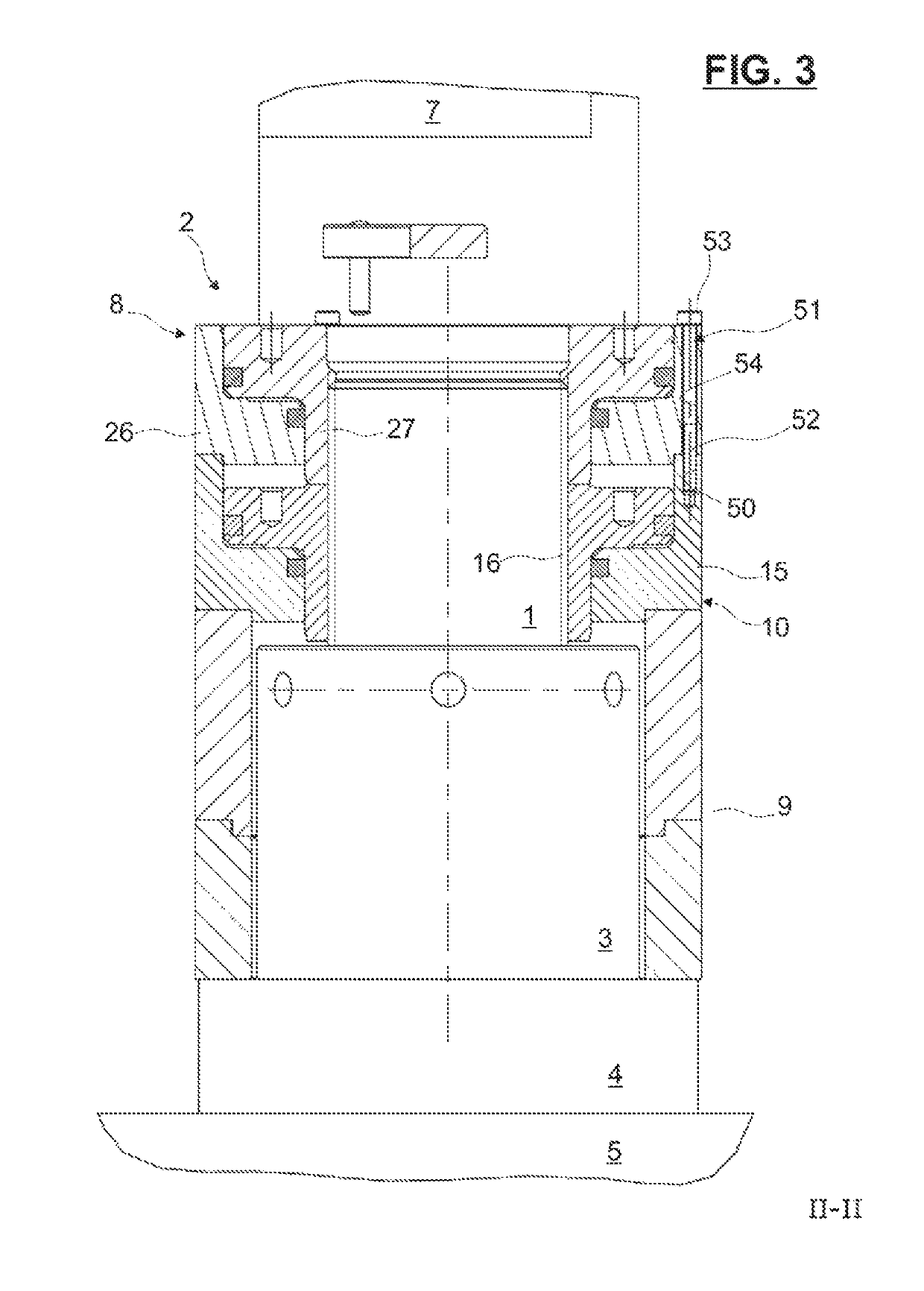
[0048]Referring first to FIGS. 1 to 3, which illustrate an example of an embodiment of a rod tensioning device according to the invention, a threaded rod 1 axially protrudes from a structure 4 and is to be axially pre-stressed using a tensioning device referred generally as 2 and thereafter maintained in the pre-stressed state by a nut 3 resting against a surface 4a of a first structure 4 to be tightened with a second structure 5. For illustrating the dimensional constraints faced by the tensioning device, the outer structure 6 limits the radial dimension for the tensioning device 2 around the threaded rod 1 and the upper structure 7 limits the axial dimension for installing and using the tensioning device 2.

[0049]The nut 3 provides a plurality of openings 3a on its outer periphery dedicated to receive an external tool. As an alternative not illustrated, the nut 3 may be hexagonal and provided with a fitting-up wrench mounted around the nut 3. The fitting-up wrench provides internal...


PUM


Abstract

The invention concerns a rod tensioning device having a first actuator, at least a second actuator and a tubular support sleeve dedicated to radially surround a threaded rod. Each of the actuators provides a cylinder, and a piston sliding in the cylinder and forming with the cylinder an annular chamber dedicated to be supplied with pressurized fluid. According to the invention, the at least second actuator is temporary axially arranged between the first actuator and the tubular support sleeve for a temporary blockwise assembly, the pistons of two axially adjacent actuators being indexed in rotation together.

Description

CROSS REFERENCE TO RELATED APPLICATIONS[0001]This application claims priority to German patent application no. 102016205086.9 filed on Mar. 29, 2016, the contents of which are fully incorporated herein by reference.FIELD OF THE INVENTION[0002]The present invention concerns a device for tensioning a rod before the rod is tightened in position, for example with a nut. More particularly, the invention relates to pre-stressed threaded rods used to tighten two mechanical structures together. These threaded rods may be used particularly in wind turbines or nuclear reactors in order to maintain firmly two mechanical structures together. Such a rod tensioning device is disclosed at GB 2 143 608 A.BACKGROUND OF THE INVENTION[0003]The tensioning of the rods can be done by applying a tightening torque to nuts resting axially on the surfaces of the structures to be tightened. The tensioning rod device exerts an axial tensile for to one end of the threaded rod by means of a tie-rod. The device r...

Claims


Application Information

Patent Timeline
Patent Type & Authority Patents(United States)
IPC IPC(8): B23P19/06B25B29/02
CPCB25B29/02B23P19/067
Inventor ALEGRE, MARC
Owner AB SKF
Why Eureka
Try Eureka