Supercharge Your Innovation With Domain-Expert AI Agents!

Clip and fixing mechanism

a fixing mechanism and clip technology, applied in the field of clips, can solve the problems of difficult insertion of inserts, and achieve the effect of convenient insertion work

Active Publication Date: 2019-04-02
KITAGAWA INDS
View PDF10 Cites 4 Cited by
  • Summary
  • Abstract
  • Description
  • Claims
  • Application Information

AI Technical Summary

Benefits of technology

This patent describes a clip that can be soldered to a printed wiring board and used to hold an insert. The clip has a contact surface that guides the insert to a position between the first and second spring pieces, making the insertion process easier. The contact surface is positioned between the two holding portions, preventing an increase in the size of the clip. The clip can accommodate a variety of inserts without requiring a precise alignment of the insert and the holding portion. Overall, the technology provides a simple and efficient solution for holding inserts in printed wiring boards.

Problems solved by technology

However, in each of the holding spring portions, the portion extending upward from the bottom surface and a significant portion of the bending portion of the leading edge thereof do not have the guiding function described above.
As a result, a range of the guiding function is small with respect to a size of the clip, and insertion of the insert tends to become difficult.

Method used


Image

  • Clip and fixing mechanism
  • Clip and fixing mechanism
  • Clip and fixing mechanism

Examples


first embodiment

1. First Embodiment

1-1. Overall Configuration

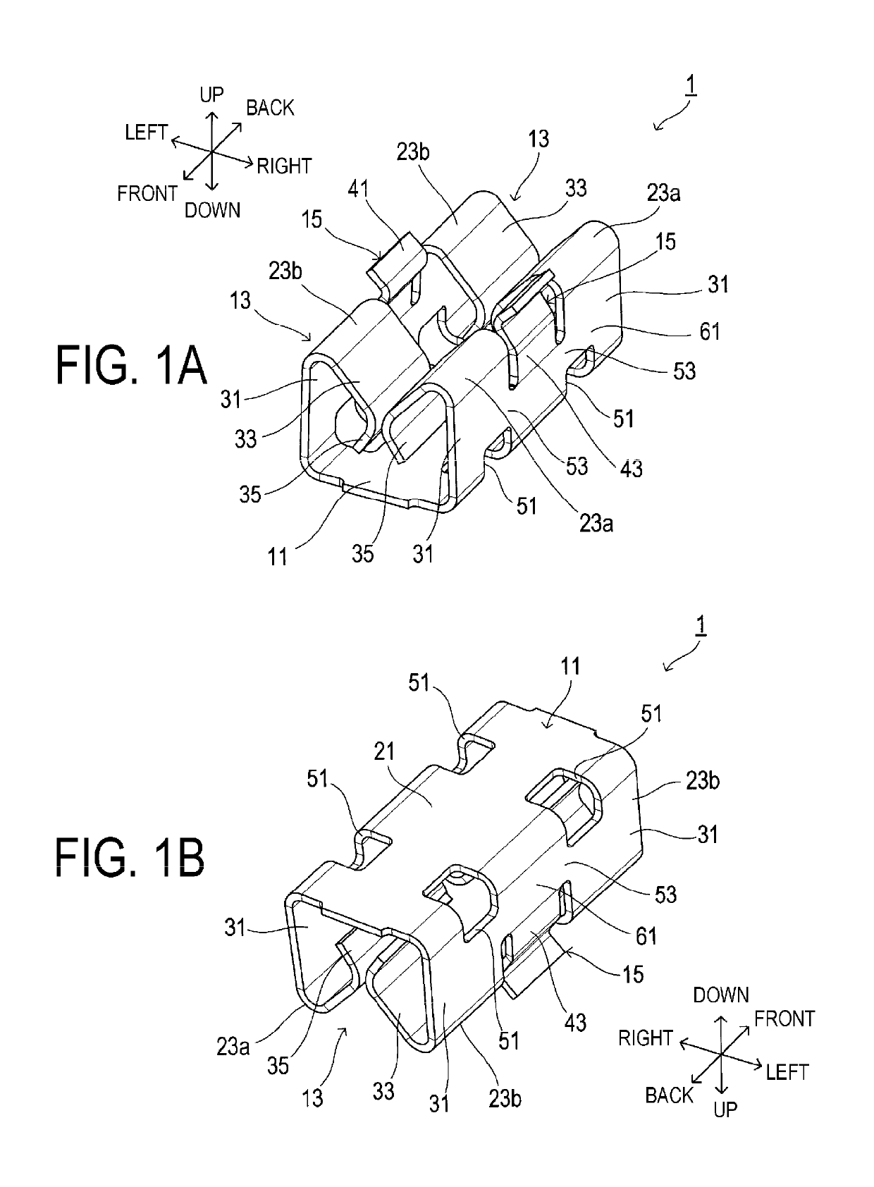
[0030]A clip 1 illustrated in FIGS. 1A, 1B, and 2A to 2D is surface mounted to a conductive portion of a printed wiring board by soldering, and functions as a clip that sandwiches and holds an insert serving as the object to be held on the printed wiring board.

[0031]The conductive portion corresponds to a portion of the printed wiring such as a copper layer that connects electronic parts mounted to the printed wiring board. When the insert described above is a conductive member, the conductive portion described above and the insert can be electrically connected.

[0032]The clip 1 is conceivably formed by press-processing a sheet metal having electrical conductivity. Note that the material and formation method of the clip 1 are not particularly limited.

[0033]The clip 1 includes a base portion 11, holding portions 13, guiding portions 15, and the like. While the configuration of the clip 1 is hereinafter described using directions such as fro...

second embodiment

2. Second Embodiment

2-1. Differences from First Embodiment

[0070]The configuration of the second embodiment is fundamentally the same as the configuration of the first embodiment. As such, description will be focused on differences and description of configurations that are the same will be omitted. Note that reference numerals in the present embodiment that are the same as those used in the first embodiment refer to the same constituents, and reference is made to the preceding description.

[0071]In the first embodiment described above, a configuration in which the contact surface 41 is disposed in a position between the two holding portions 13 in relation to the front-back direction is illustrated as an example. In contrast, the second embodiment differs from the first embodiment in that a contact surface is formed on the spring pieces as well.

[0072]As illustrated in FIGS. 8A and 8B, a clip 101 includes two holding portions 103, and the holding portions 103 each include a pair of spr...


PUM


Abstract

A clip is provided with a base portion, at least one holding portion, and a guiding portion. The holding portion includes spring pieces including a first and second spring pieces connected to the base portion and facing each other, and sandwiches an insert inserted between these spring pieces. The guiding portion includes a contact surface that guides the insert toward a position between the first and second spring pieces when the insert moves in an insertion direction and the guide portion comes into contact with the insert. The contact surface is at least partially in a position farther away from the base portion than the second portion of at least one of the first or second spring pieces. The contact surface is at least partially, in relation to a facing direction, in a position farther away from the corresponding spring piece than the second portion of the one spring piece.

Description

CROSS-REFERENCE TO RELATED APPLICATION[0001]This application is the U.S. national stage of international application number PCT / JP2016 / 088425, filed on Dec. 22, 2016, which claims priority to Japanese Patent Application No. 2015-253813A, filed to Japan Patent Office on Dec. 25, 2015, and the total contents of each are hereby incorporated by reference.TECHNICAL FIELD[0002]The present disclosure relates to a clip that is to be soldered to a printed wiring board and used for fixing a shielding case or the like.BACKGROUND ART[0003]In the related art, clips that are to be soldered to a printed wiring board and used for fixing a shielding case or the like have been utilized. In Japanese Unexamined Patent Application Publication No. 2013-168508A, there is described a clip that includes holding spring portions that form a pair and are disposed facing each other. The holding spring portions of this clip each extend upward from a bottom surface, with an extended tip thereof bent inward and do...

Claims


Application Information

Patent Timeline
Patent Type & Authority Patents(United States)
IPC IPC(8): H01R12/00F16B2/24H05K7/12H05K9/00H01R12/57H01R4/48F16B1/00
CPCH05K7/12F16B1/00F16B2/245H01R12/57H05K9/0007H01R4/48F16B2001/0064F16B5/06H05K1/18H05K9/0035F16B2200/93
Inventor NAKAMURA, TATSUYA
Owner KITAGAWA INDS
Features
  • R&D
  • Intellectual Property
  • Life Sciences
  • Materials
  • Tech Scout
  • Unparalleled Data Quality
  • Higher Quality Content
  • 60% Fewer Hallucinations
Learn More