Supercharge Your Innovation With Domain-Expert AI Agents!

Staple remover

a technology of staples and spouts, which is applied in the field of staple removers, can solve the problems of insufficient protruding staples, difficult to remove from the post, and insufficient protruding staples, and achieve the effect of less physical force of users, faster and easier removal of larger staples with barbed ends

Active Publication Date: 2019-04-09
HUGHES ALAN JAMES
View PDF10 Cites 0 Cited by
  • Summary
  • Abstract
  • Description
  • Claims
  • Application Information

AI Technical Summary

Benefits of technology

The patent text describes a device for removing staples from a fence post. The device has a main body with a block portion on its surface that aligns with the closed end of the first channel, increasing the contact area between the device and the wire. The lever is an elongate member that users can hold and apply force to remove staples. The second position keeps the edge of the device's gripping member away from the surface of the wire to prevent crushing it. The device also has a strut member between the first and second claws to provide strength.

Problems solved by technology

The barb digs into the post and as a result makes it harder to remove from the post by adding to the drag of the staple.
One reason for doing this is if the fence posts become damaged, e.g. through general wear over time, or if they become damaged as a result of contact with cattle.
Therefore it can be an extremely time consuming and fiddly process.
However a disadvantage associated with the use of fencing pliers is that they often end up breaking the top of the staple, after which the broken parts of the staple have to be removed with conventional pliers.
Furthermore, many staples are hammered well into the surface of the post, and in such instances not enough of the staple is protruding to allow the jaws of the fencing pliers to grip the staple.
Moreover, the use of fencing pliers for staple removal can be a fiddly, awkward, and time-consuming operation, and especially so when removing staples / wires from fence battens, which are prone to moving about during the operation of removing the staple.
However, it is sometimes difficult to force the claw of the hammer behind the wire of the staple.
Furthermore, a claw hammer is ineffective in situations where the wire is loosely broken.
Moreover the use of a claw hammer is ineffective in situations where the wire is loose or broken.
Moreover, the use of a claw hammer for staple / wire removal can be a fiddly, awkward, and time-consuming operation, and especially so when removing staples / wires from fence battens, which are prone to moving about during the operation of removing the staple / wire.
However, the known staple remover can only pull out staples of a certain size for example small staples under 15 mm long which are generally applied to square posts, commonly used in New Zealand.
The known staple remover is inefficient at successfully removing the long, barb ended staples in one piece.
As a result the wire is cut at the contact points and the tool loses its ability to remove the staple by means of the wire.
Also, the known staple remover can only be applied to square posts and to remove staples above 200 mm from ground level.
Any staples located lower than 200 mm above ground level cannot be removed using the known staple remover due to the orientation of the handle.
Further when the tool is used to pull out staples larger than 15 mm long, the claws of the tool bend inwards and are unusable again and unrepairable without great effort.
Therefore, in summary, the staple remover as shown in FIG. 1 cannot withstand the required level of force to pull the larger UK staple out of a fence post without causing damage to the known staple remover or the wire.

Method used


Image

  • Staple remover
  • Staple remover
  • Staple remover

Examples


Embodiment Construction

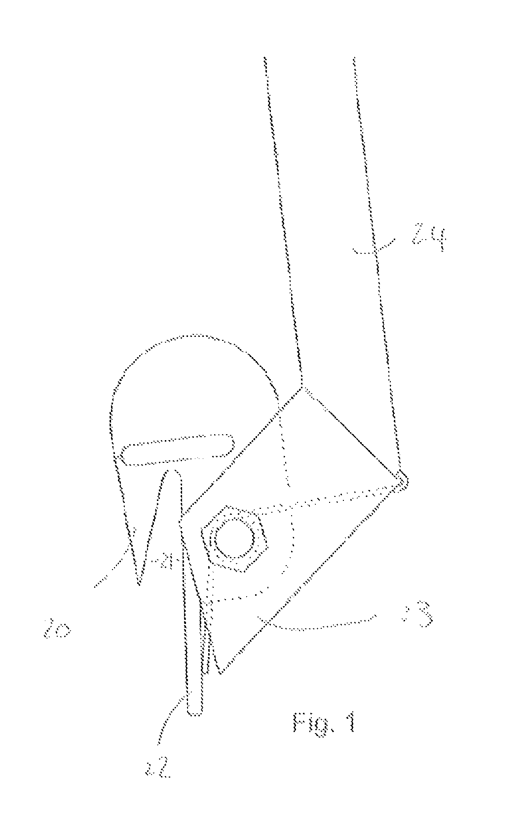
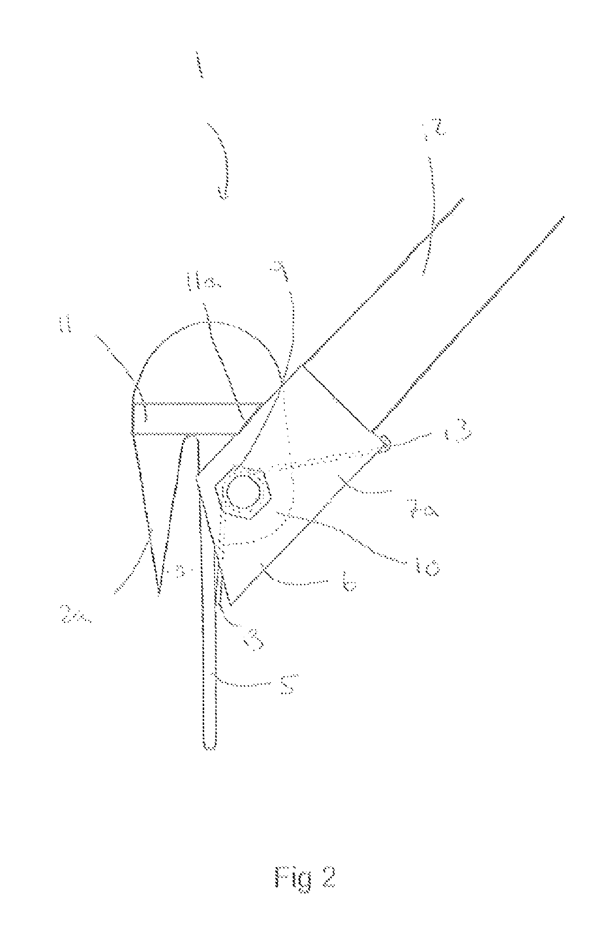
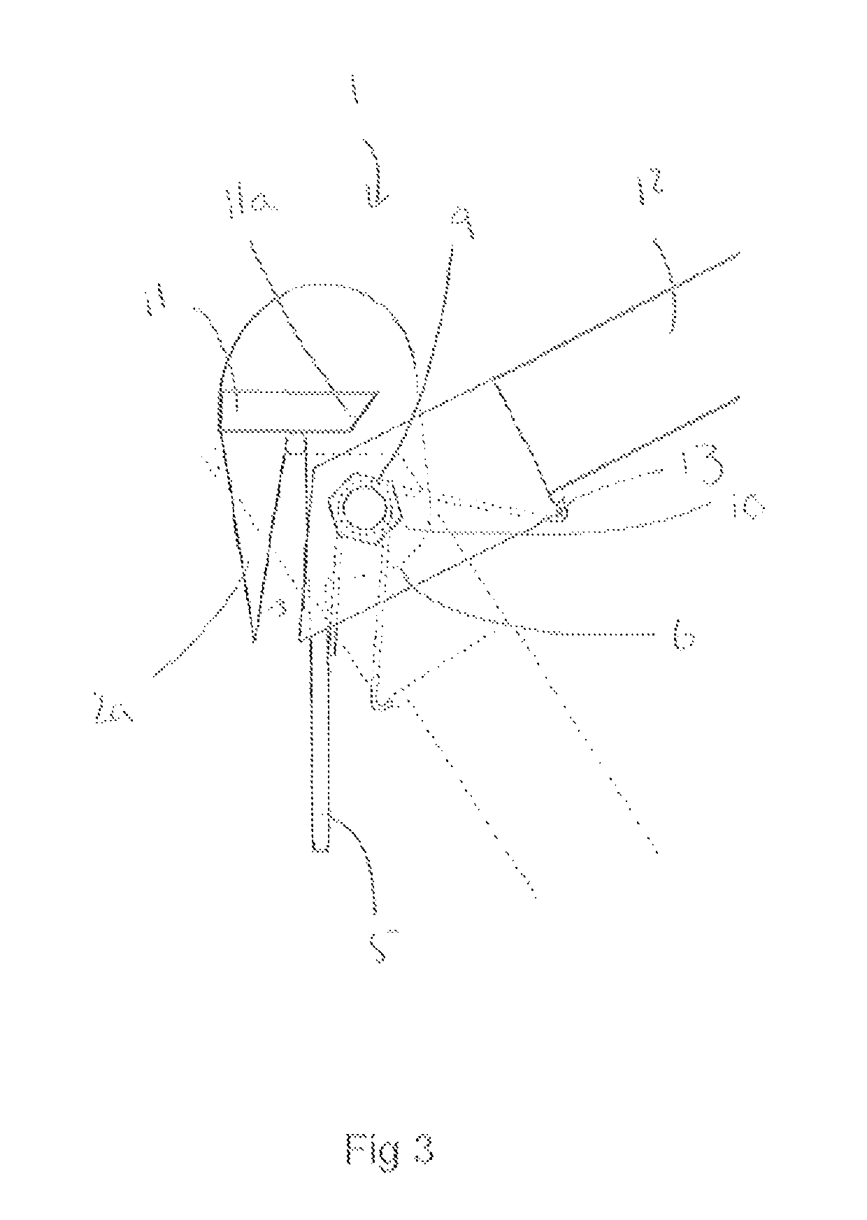
[0042]FIG. 2 and FIG. 3 shows the staple remover 1 comprising a first claw 2a and a second claw 2b which are adapted to hook onto a wire either side of a staple.

[0043]In use the claws 2a, 2b are positioned either side of the post such that the front of the post fits in the region located between the first and second claw 2a, 2b. Each claw includes a channel 3 in which the wire is located wherein each channel 3 has an open end past which the wire passes as the claws 2a, 2b are being hooked onto and over the wire, and a closed end where the wire is retained after the claws 2a, 2b have been hooked over the wire.

[0044]FIG. 4 shows a support bar 4 positioned intermediate the first and second claw 2a, 2b such that it extends between the inner surface of the first claw 2a to the inner surface of the second claw 2b. The support bar 4 braces the first and second claw 2a, 2b apart so that they cannot be bent when applied to large staples.

[0045]The staple remover 1 also includes a leverage por...


PUM


Abstract

A staple removal device for removing a staple and wire arrangement from a fence post includes a main body having a first jaw and a second jaw spaced apart from each other. The first jaw and second jaw provide a first and second elongate channel respectively for receiving the wire. Both the first and second elongate channels comprise a closed end in which the wire may be received. A gripping portion is moveably connected to the main body and a lever causes movement of the gripping portion. Beneficially, a first and second block portion is configured at a surface of the main body wherein a side edge of the first and second block portion is substantially in alignment with the closed end of the first and second channel respectively so as to, in use, increase the surface area of the contact region between the staple removal device and the wire.

Description

[0001]This application claims priority to European Patent Application No. EP16182040.2 filed Jul. 29, 2016.FIELD OF INVENTION[0002]This invention relates to a staple remover, in particular a staple remover to remove fencing staples and wires from wooden fence posts.BACKGROUND[0003]It is known to use agricultural fencing for a wide range of purposes, for example to contain livestock, for defining land boundaries and for fencing off waterways.[0004]A common type of agricultural fence is post and wire fencing. Such fences are built in sections whereby the farmer marks out the desired line of the fence and then places wooden strainer posts at each corner of the fence line. The strainer posts are larger, longer and heavier than other posts and have to stay in place when the fence wires are tightened or “strained”. Strainer posts are usually supported by stays, which are wooden posts that lean on an angle against the strainer post, in each direction that the fence line runs. This arrangem...

Claims


Application Information

Patent Timeline
Patent Type & Authority Patents(United States)
IPC IPC(8): B25C3/00B25C11/00E04H17/26
CPCE04H17/268B25C11/00
Inventor HUGHES
Owner HUGHES ALAN JAMES
Features
  • R&D
  • Intellectual Property
  • Life Sciences
  • Materials
  • Tech Scout
  • Unparalleled Data Quality
  • Higher Quality Content
  • 60% Fewer Hallucinations
Learn More