Check patentability & draft patents in minutes with Patsnap Eureka AI!

Radiation irradiation device

a technology of irradiation device and irradiation screen, which is applied in the direction of radiation generation arrangement, medical science, diagnostics, etc., can solve the problems of blocking the visual field in front of the user, affecting the smooth capture of the display unit, and affecting the user's experience. , to achieve the effect of smooth capture and easy input to the display uni

Active Publication Date: 2019-04-16
FUJIFILM CORP
View PDF38 Cites 2 Cited by
  • Summary
  • Abstract
  • Description
  • Claims
  • Application Information

AI Technical Summary

Benefits of technology

[0008]However, in a case where the user stands behind the body part, depending on the position of installation of the monitor to the body part, a visual field in front of the user may be blocked, and may become an obstacle. Additionally, in a case where the monitor of the touch panel type is provided, there is also a case where input to the monitor may be easier in a case where the monitor is located at a position closer to a user's dominant arm than in a case where the monitor is located at a front position with respect to the user. Moreover, in a case where the user changes the position of a radiation source attached to the tip of the arm part or performs an input operation on an operating part provided at the radiation source, and in a case where the user moves from the rear of the body part to the front side, there is a case where the monitor provided on the body part may become an obstacle and may not easily move smoothly. Additionally, in a case where the user changes the position of the radiation source or in a case where the user is performing an input operation on the operating part, the user moves to the front side of the device. Thus, there is a case where it may be difficult to view the display of the monitor.
[0010]An object of the invention is to provide a radiation irradiation device enabling a user to change the position of a monitor to a desired position as needed and smoothly perform imaging of a radiographic image, in view of the above problems.
[0029]According to the radiation irradiation device of the invention, the display unit can be detachably installed at the plurality of positions on the surface that faces the bottom surface of the body part. Thus, a user can change the position of the display unit to the desired position as needed. Accordingly, a radiographic image can be smoothly captured while viewing the display of the display unit, for example, without the display unit becoming an obstacle. Additionally, the monitor can be installed at a position where the user can see easily.
[0030]Additionally, in a case where the display unit is of a touch panel type, input to the display unit becomes easy by installing the display unit at a position closer to a user's dominant arm.

Problems solved by technology

Thus, the position of the monitor cannot be changed.
However, in a case where the user stands behind the body part, depending on the position of installation of the monitor to the body part, a visual field in front of the user may be blocked, and may become an obstacle.
Moreover, in a case where the user changes the position of a radiation source attached to the tip of the arm part or performs an input operation on an operating part provided at the radiation source, and in a case where the user moves from the rear of the body part to the front side, there is a case where the monitor provided on the body part may become an obstacle and may not easily move smoothly.
Thus, there is a case where it may be difficult to view the display of the monitor.
That is, in a case where the position of the monitor is fixed with respect to the body part, there is a case where the monitor may become an obstacle for a certain reason or it may be difficult to view the display of the monitor.

Method used


Image

  • Radiation irradiation device
  • Radiation irradiation device
  • Radiation irradiation device

Examples


Embodiment Construction

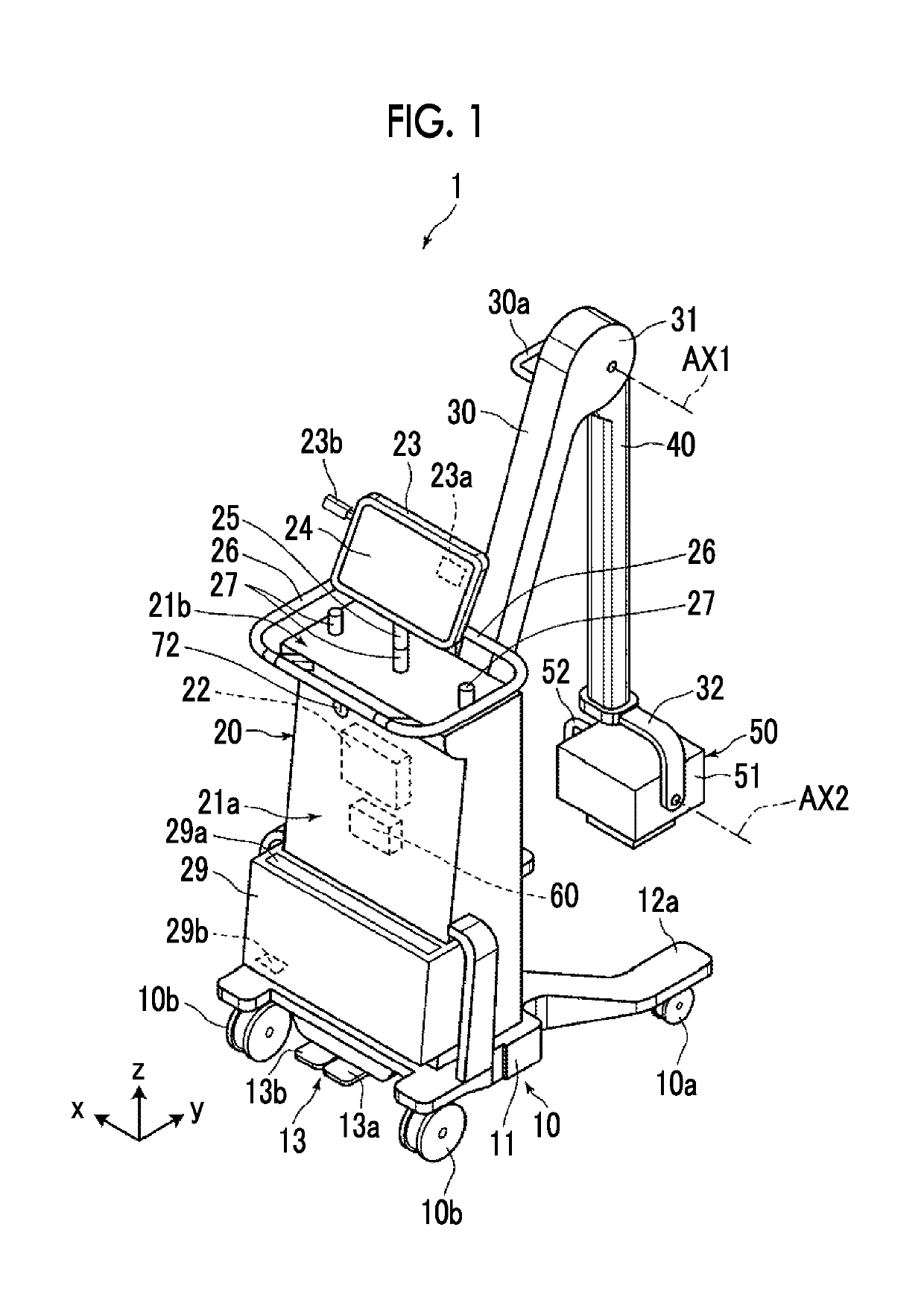
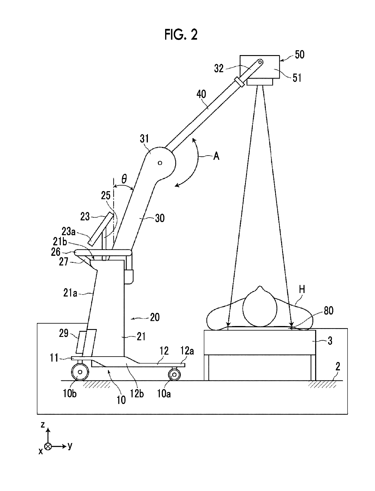
[0040]Hereinafter, a radiation irradiation device of an embodiment of the invention will be described in detail, referring to the drawings. FIG. 1 is a perspective view illustrating the entire shape of the radiation irradiation device of the present embodiment in a case where the device is not used, and FIG. 2 is a side view illustrating the state of the radiation irradiation device of the present embodiment in a case where the device is used. In addition, in the following, an upper side and a lower side in the vertical direction in a state where the radiation irradiation device is placed, for example, a device placement surface, such as a floor of a medical institution, are referred to as “up” and “down”, respectively, and a direction perpendicular to the vertical direction in the same state is referred to as a “horizontal” direction. Additionally, in the views to be described below, the vertical direction is defined as a z direction, a right and left direction of the radiation irr...


PUM


Abstract

Provided is a radiation irradiation device enabling a user to change the position of a monitor to a desired position as needed and smoothly perform imaging of a radiographic image. The radiation irradiation device includes a radiation generation unit that generates radiation; a second support part having one end to which the radiation generation unit is attached; a first support part having one end to which the second support part is connected and the other end connected to a body part; the body part; a leg part that is provided on a bottom surface of the body part and is capable of traveling on a device placement surface; and a monitor provided on a surface that faces the bottom surface of the body part, via a connecting member. The monitor is detachably installed at a plurality of positions on the surface that faces the bottom surface of the body part.

Description

CROSS-REFERENCE TO RELATED APPLICATIONS[0001]This application is a Continuation of PCT International Application No. PCT / JP2016 / 083458 filed on Nov. 11, 2016, which claims priority under 35 U.S.C § 119(a) to Japanese Patent Application No. 2015-230364 filed on Nov. 26, 2015 and Japanese Patent Application No. 2016-079511 filed on Apr. 12, 2016. Each of the above application(s) is hereby expressly incorporated by reference, in its entirety, into the present application.BACKGROUND OF THE INVENTION1. Field of the Invention[0002]The present invention relates to a radiation irradiation device having an arm part provided with a radiation source.2. Description of the Related Art[0003]In the related art, portable radiation irradiation devices used in a case where a patient's radiographic image is captured in operating rooms, examination rooms, or patients rooms have been suggested variously (refer to JP2014-204783A, JP2015-83113A, and JP2006-55201A).[0004]The portable radiation irradiation ...

Claims


Application Information

Patent Timeline
Patent Type & Authority Patents(United States)
IPC IPC(8): A61B6/00A61B90/50
CPCA61B6/4405A61B6/00A61B90/50A61B6/462A61B6/563A61B6/40
Inventor ONOBORI, NORIYUKIOGURA, RYOSUKEKOBAYASHI, TAKEYASUKITAGAWA, YUSUKE
Owner FUJIFILM CORP
Features
  • R&D
  • Intellectual Property
  • Life Sciences
  • Materials
  • Tech Scout
  • Unparalleled Data Quality
  • Higher Quality Content
  • 60% Fewer Hallucinations
Learn More