LNG export terminal

a technology of lng export terminal and lng port, which is applied in the direction of liquid handling, transportation and packaging, packaging goods type, etc., can solve the problems of difficult to provide facilities onshore, limited facilities on the barge, and risk of damage to the barge during the journey

Inactive Publication Date: 2019-04-16
SINGLE BUOY MOORINGS INC
View PDF9 Cites 0 Cited by
  • Summary
  • Abstract
  • Description
  • Claims
  • Application Information

AI Technical Summary

Benefits of technology

[0003]It is an object of the present invention is to provide an improved liquefied natural gas (LNG) export terminal which reduces the disadvantages and limitations of the LNG export terminals, known from the prior art.
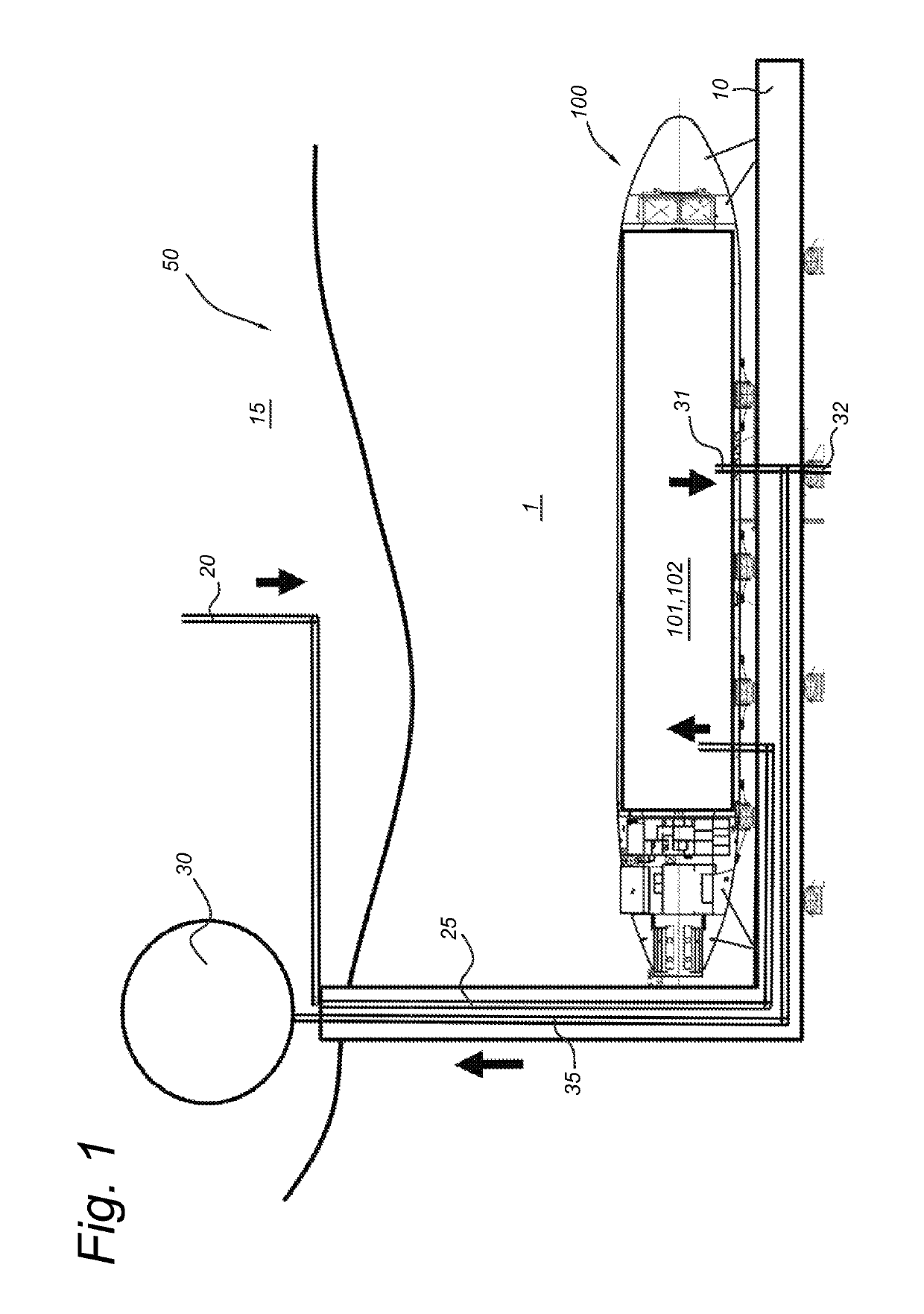
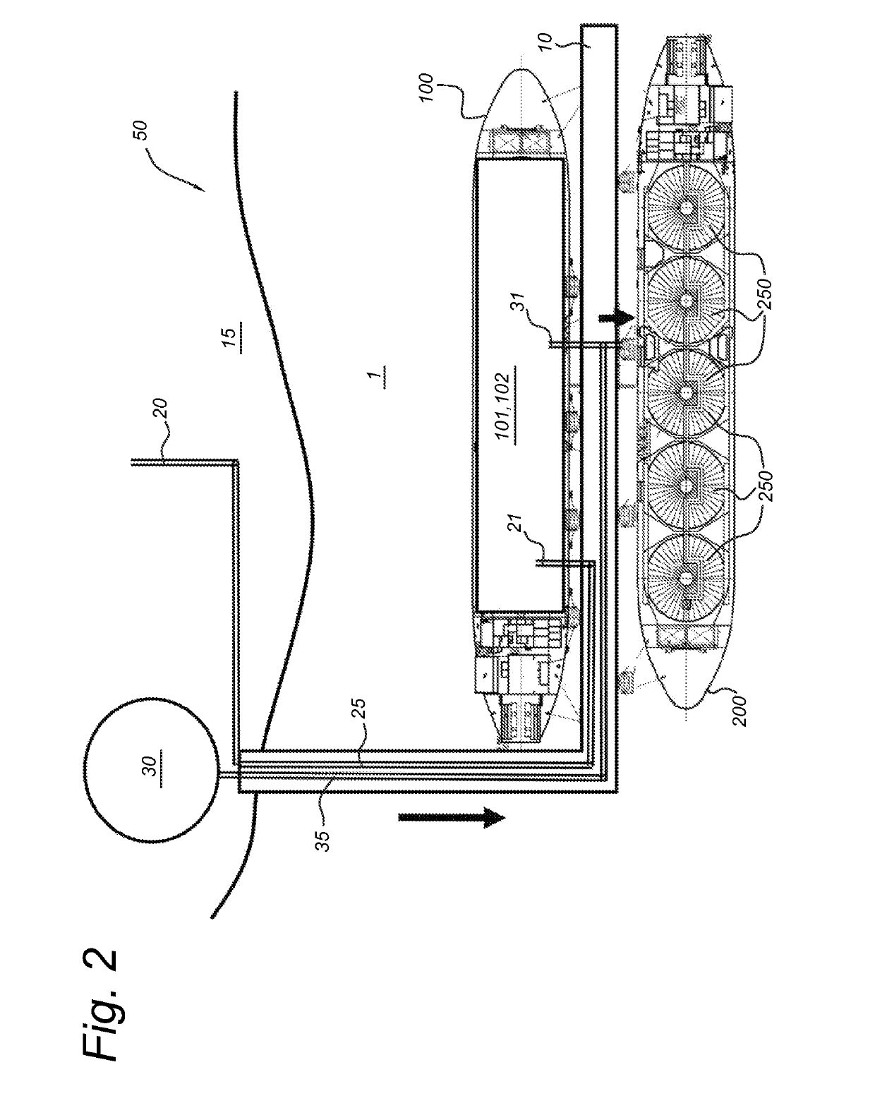
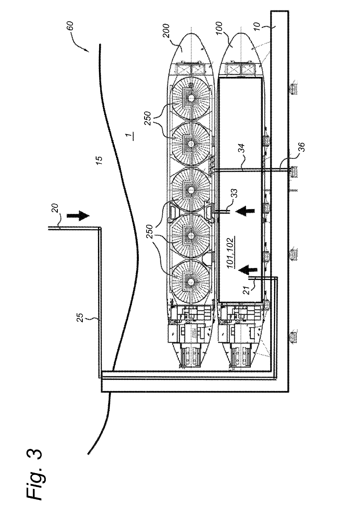
[0005]The inventors have observed that instead of using a flat-top barge, as described in the prior art, the use of a converted hydrocarbon carrier-vessel as a platform for the natural gas processing system for liquefying natural gas offers the advantage that some functionalities of the converted hydrocarbon carrier-vessel can be re-used and have to be newly built on a flat-top barge, such as, but not limited to, a deckhouse for operational people on board, possibly only during dayshift, going home after work, supporting facilities for people on-board (drinking water, sewage treatment), safety systems in the accommodation area, boiler (to provide process heat and for start-up), and emergency power supply.

Problems solved by technology

The barges described in U.S. Pat. No. 2,940,268 are often custom made in specialized wharfs and they mostly lack proper propulsion to reach their operational destination, so that they need to be towed or transported, sometimes over large distances.
The risk of damage to the barge during the journey to the operational destination is clear and present.
Furthermore, the facilities provided on the barge are limited and it may be necessary to provide extensive facilities onshore.
Providing facilities onshore is difficult and / or requires important investments on some operational sites.

Method used


Image

  • LNG export terminal
  • LNG export terminal
  • LNG export terminal

Examples


Embodiment Construction

[0025]The present invention will be described with respect to particular embodiments and with reference to certain drawings but the invention is not limited thereto. The drawings described are only schematic and are non-limiting. In the drawings, the size of some of the elements may be exaggerated and not drawn on scale for illustrative purposes.

[0026]Furthermore, the terms first, second, third and the like in the description are used for distinguishing between similar elements and not necessarily for describing a sequential or chronological order. The terms are interchangeable under appropriate circumstances and the embodiments of the invention can operate in other sequences than described or illustrated herein.

[0027]Moreover, the terms top, bottom, over, under and the like in the description are used for descriptive purposes and not necessarily for describing relative positions. The terms so used are interchangeable under appropriate circumstances and the embodiments of the invent...


PUM


Abstract

A near shore liquefied natural gas (LNG) export terminal includes an LNG storage unit, a jetty and a converted hydrocarbon carrier-vessel moored against the jetty. The carrier-vessel includes a hull, at least one hydrocarbon storage tank and is provided with a natural gas processing system for liquefying natural gas. Onshore produced natural gas is supplied through a first pipeline to the natural gas processing plant on the carrier-vessel and the LNG produced by the natural gas processing system is transferred from the carrier-vessel to the LNG storage unit via a second pipeline suitable for the transfer of cryogenic fluids.

Description

FIELD OF THE INVENTION[0001]The present invention relates to an near shore LNG export terminal, comprising a floating natural gas processing system and an LNG storage unit.BACKGROUND[0002]Such terminals have been described in the prior art. U.S. Pat. No. 2,940,268, for example, teaches to liquefy of natural gas in a barge mounted liquefaction plant and to subsequent discharge the liquefied natural gas into suitably insulated storage tanks, preferably installed on a tank carrying vessel. The barges described in U.S. Pat. No. 2,940,268 are often custom made in specialized wharfs and they mostly lack proper propulsion to reach their operational destination, so that they need to be towed or transported, sometimes over large distances. The risk of damage to the barge during the journey to the operational destination is clear and present. Furthermore, the facilities provided on the barge are limited and it may be necessary to provide extensive facilities onshore. Providing facilities onsh...

Claims


Application Information

Patent Timeline
Patent Type & Authority Patents(United States)
IPC IPC(8): F17C3/00F17C6/00
CPCF17C6/00F17C2201/0128F17C2221/033F17C2270/0136F17C2270/0105F17C2270/0113F17C2270/0123F17C2223/0161
Inventor WYLLIE, MICHAELBRINKEL, THEODORUS JOHANNES BERNARDUS
Owner SINGLE BUOY MOORINGS INC
Why Eureka
Try Eureka