Developer container, developing apparatus, process cartridge and image forming apparatus
a development apparatus and container technology, applied in electrographic process apparatus, instruments, optics, etc., can solve the problems of increasing the amount of toner laying on the stirring member, increasing the rotation radius of the stirring member, and shortening the service life so as to increase the capacity of the toner storing chamber, increase the rotation radius of the stirring member, and increase the bending amount of the stirring member
- Summary
- Abstract
- Description
- Claims
- Application Information
AI Technical Summary
Benefits of technology
Problems solved by technology
Method used
Image
Examples
example 1
[0046]Electro-photographic Image Forming Apparatus 100
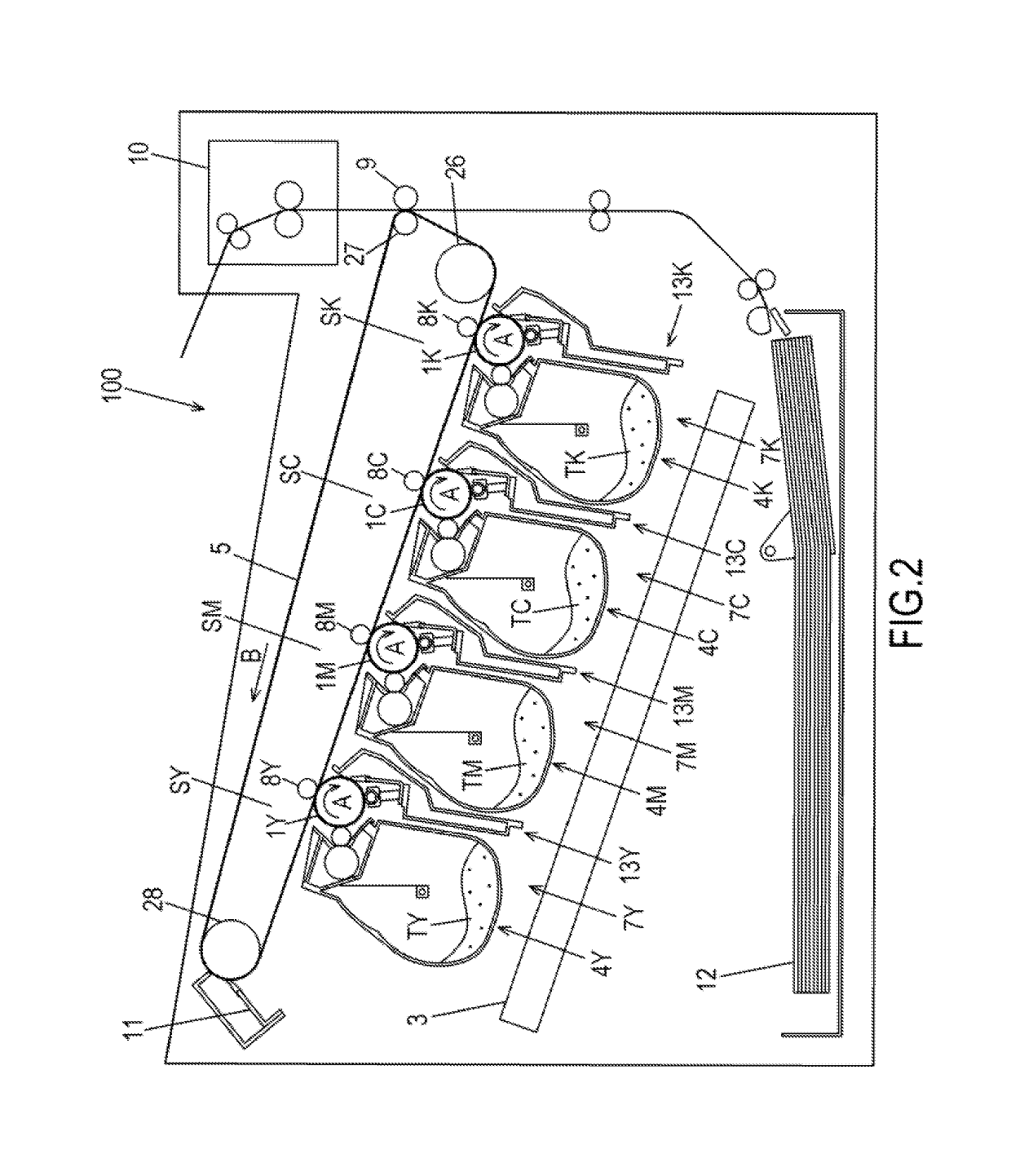
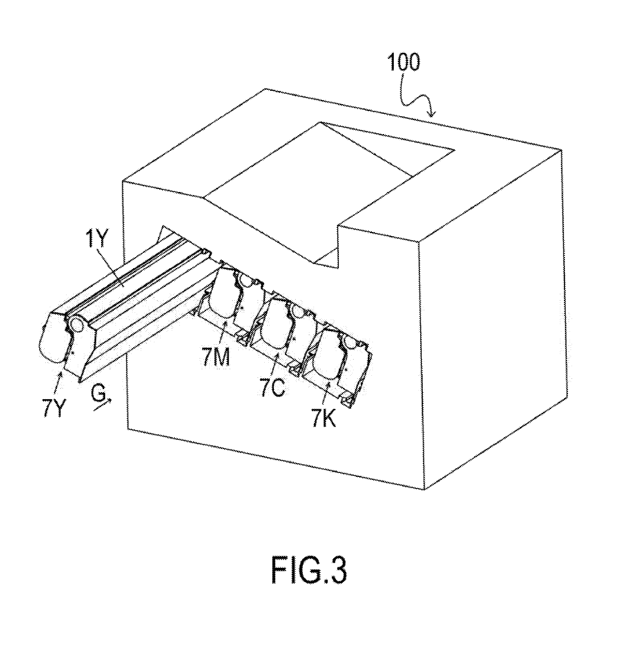
[0047]A general configuration of an electro-photographic image forming apparatus 100 (image forming apparatus 100) according to Example 1 will be described with reference to FIG. 2 and FIG. 3. FIG. 2 is a schematic diagram of the image forming apparatus 100 according to Example 1. FIG. 3 is a perspective view depicting a state of installing a process cartridge 7 in the image forming apparatus 100. The image forming apparatus 100 has a plurality of image forming portions SY to SK, which are first to fourth image forming portions for forming yellow (Y), magenta (M), cyan (C) and black (K) images respectively.
[0048]In Example 1, the first to fourth image forming portions have substantially the same configuration and perform the same operation, except that the color of the image to be formed is different. Therefore in the following description, the suffixes Y to K are omitted unless distinction is necessary. In Example 1, the image f...
example 2
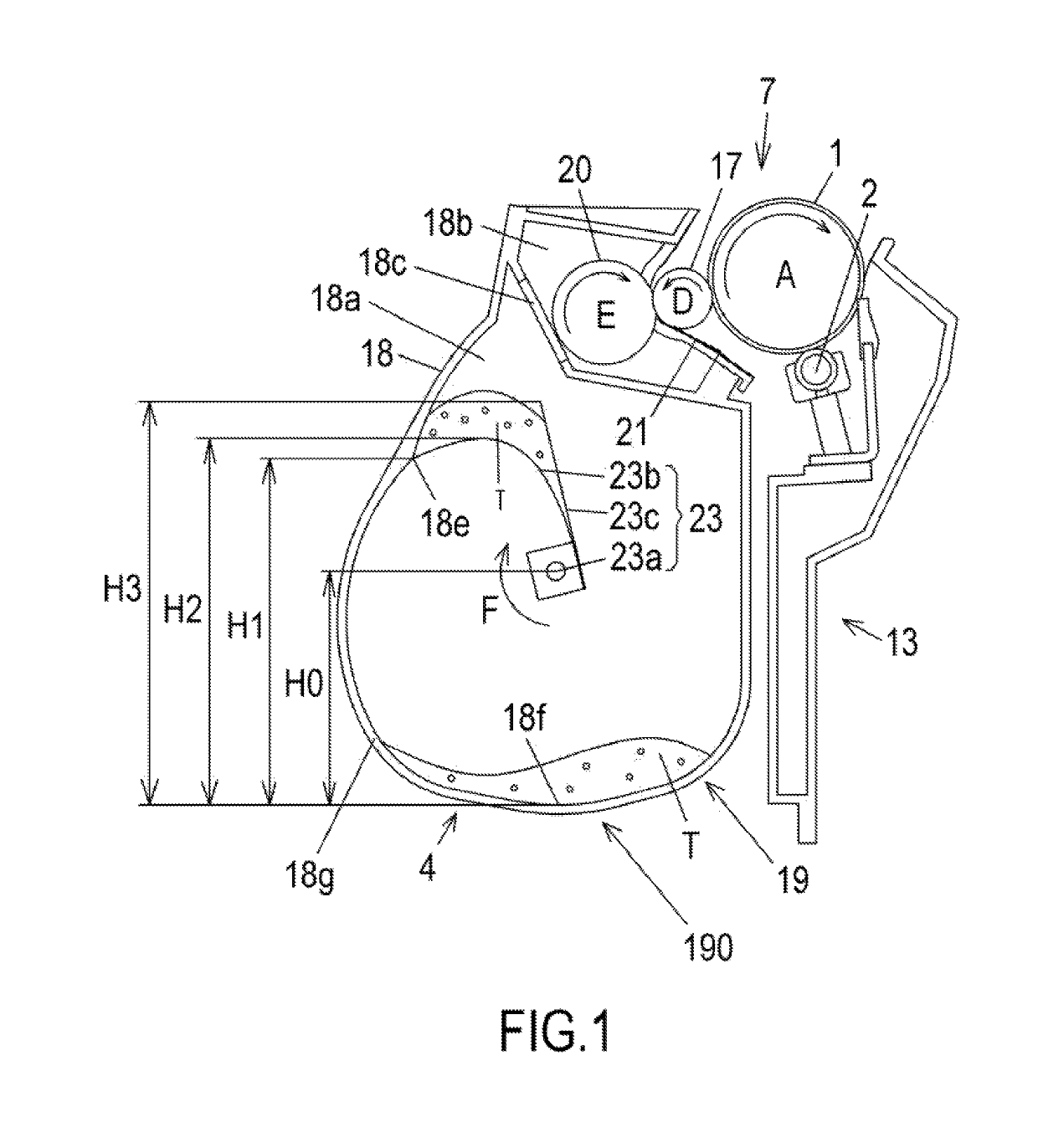
[0083]Example 2 will be described next. In Example 2, the basic configurations of the image forming apparatus and the process cartridge are the same as Example 1. Therefore in Example 2, a composing element having the same function as Example 1 is denoted with the same reference sign, and description thereof is omitted. FIG. 8 is a schematic cross-sectional view of the process cartridge according to Example 2. In Example 2, as illustrated in FIG. 8, a concave portion 18d is disposed in the toner storing chamber 18a, as a means of detecting the residual toner amount in the toner storing chamber 18a. The concave portion 18d is disposed on the upstream side of the release position 18e in the rotating direction of the stirring member 230. The concave portion 18d is also disposed in such a position that the toner on the stirring sheet 23b enters the concave portion 18d in the process of the stirring sheet 23b rotating with elevating the toner.
[0084]When the residual toner amount inside t...
PUM
 Abstract
Description
Claims
Application Information
 - R&D
- Intellectual Property
- Life Sciences
- Materials
- Tech Scout
- Unparalleled Data Quality
- Higher Quality Content
- 60% Fewer Hallucinations
Browse by: Latest US Patents, China's latest patents, Technical Efficacy Thesaurus, Application Domain, Technology Topic, Popular Technical Reports.
© 2025 PatSnap. All rights reserved.Legal|Privacy policy|Modern Slavery Act Transparency Statement|Sitemap|About US| Contact US: help@patsnap.com


