Height adjustment mechanism, platform and method
a technology of height adjustment and platform, applied in the field of height adjustment mechanism, platform and method, can solve the problems of limited lifting height, and complex structure of the height adjustment platform, and achieve the effect of solving laborious and operating inconvenience, simple structure and strong practicality
- Summary
- Abstract
- Description
- Claims
- Application Information
AI Technical Summary
Benefits of technology
Problems solved by technology
Method used
Image
Examples
first embodiment
[0051]
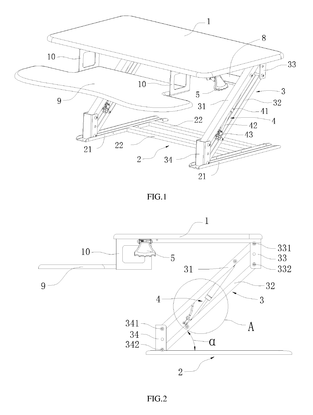
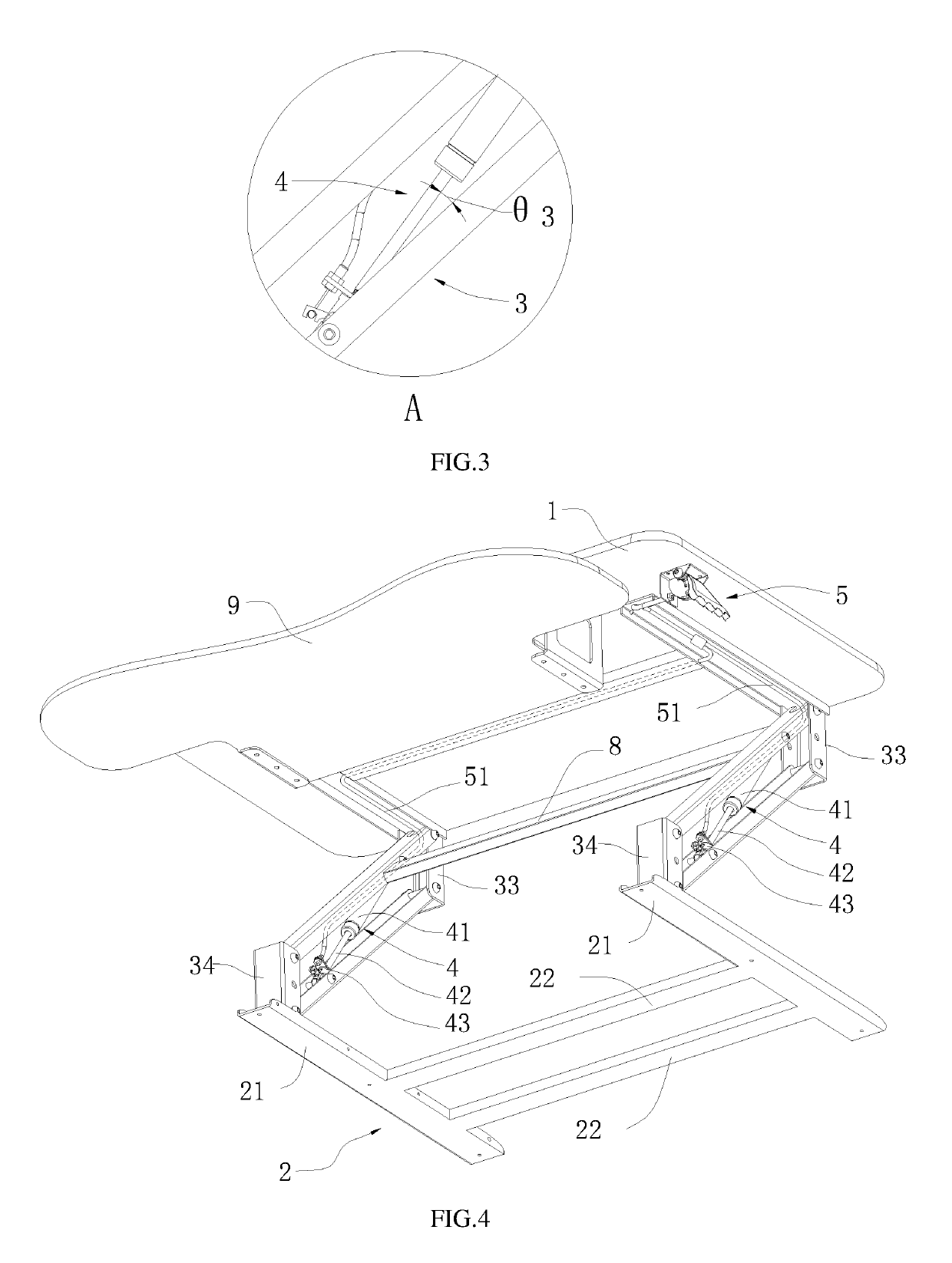
[0052]FIGS. 1-5 illustrate a height adjustment platform of a first embodiment. The height adjustment platform can include a first working table 1, a bottom bracket 2, two lifting arms 3, two driving mechanisms used to drive the lifting arms 3, and a control switch 5 configured to control the driving mechanism. Two ends of each lifting arm 3 can be rotatably coupled to the first working table 1 and the bottom bracket 2, respectively. When in use, the lifting arms 3 and the bottom bracket 2 can rotate an angle α ranging from about 0 to about 60 degrees. The driving mechanism can be mounted on one lifting arm 3, and there can be an angle θ3 formed between the driving mechanism and the corresponding lifting arm 3.
[0053]The lifting arm 3 can include a first rod 31, a second rod 32, a first joint device 33, and a second joint device 34. The first rod 31 can be parallel to the second rod 32. Two ends of the first rod 31 can be respectively coupled to the first joint device 33 and the...
second embodiment
[0067]
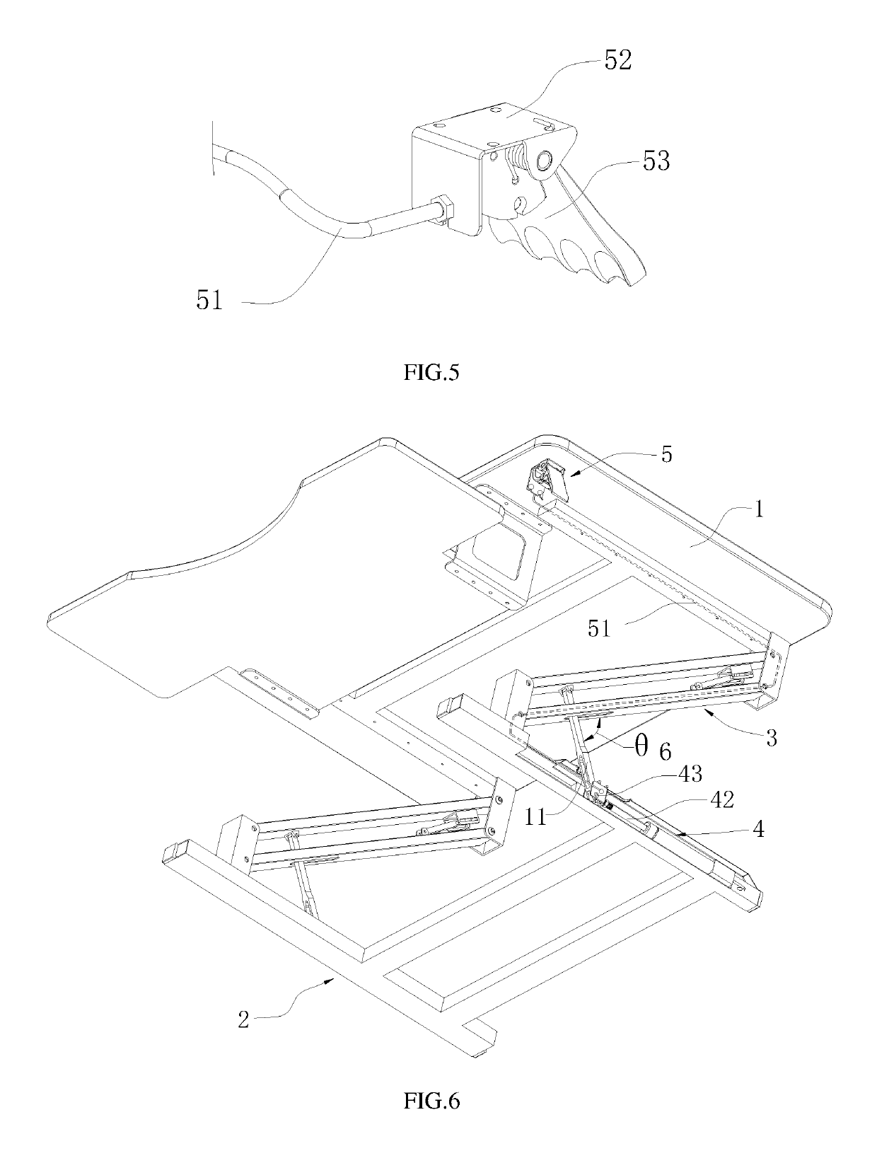
[0068]FIG. 6 illustrates a height adjustment platform of a second embodiment similar to the height adjustment platform of the first embodiment. The difference can be that the self-locking gas spring 4 used as the driving mechanism can be positioned on the bottom bracket 2, the driving mechanism can include a support rod 11. A first end of the support rod 11 can be coupled to the releasing head 43, and a second end of the support rod 11 can extend into the parallelogram structure to connect the rod of the lifting arm 3. An angle θ6 can be formed between the support rod 11 and the rod of the lifting arm 3.
[0069]When in use, the releasing rod 42 of the self-locking gas spring 4 can extend to jack up the lifting arm 3 and the working table via the support rod 11, or the releasing rod 42 of the self-locking gas spring 4 can shrink to move down the lifting arm 3 and the working table via the support rod 11.
[0070]The driving mechanism can be positioned on the bottom bracket 2 to prev...
third embodiment
[0072]
[0073]FIG. 7 illustrates a height adjustment platform of a third embodiment similar to the height adjustment platform of the first embodiment. The difference can be that the self-locking gas spring 4 used as the driving mechanism can be positioned outside of the parallelogram structure, for example, the self-locking gas spring 4 can be positioned on the bottom bracket 2. The self-locking gas spring 4 can be coupled to the rod of the lifting arm 3, and an angle θ7 can be formed between the rod of the lifting arm 3 and self-locking gas spring 4.
[0074]Other aspects of this embodiment are like those of the first embodiment.
PUM
 Abstract
Description
Claims
Application Information
 - R&D
- Intellectual Property
- Life Sciences
- Materials
- Tech Scout
- Unparalleled Data Quality
- Higher Quality Content
- 60% Fewer Hallucinations
Browse by: Latest US Patents, China's latest patents, Technical Efficacy Thesaurus, Application Domain, Technology Topic, Popular Technical Reports.
© 2025 PatSnap. All rights reserved.Legal|Privacy policy|Modern Slavery Act Transparency Statement|Sitemap|About US| Contact US: help@patsnap.com


