
Pump assembly

a technology for assembling parts and bearings, applied in the direction of sliding contact bearings, non-positive displacement fluid engines, liquid fuel engine components, etc., can solve the problem that the bearing holder is not designed as a solid material, and achieve the effect of convenient formation

Active Publication Date: 2019-04-30
GRUNDFOS HLDG
View PDF14 Cites 0 Cited by
  • Summary
  • Abstract
  • Description
  • Claims
  • Application Information

AI Technical Summary

Benefits of technology

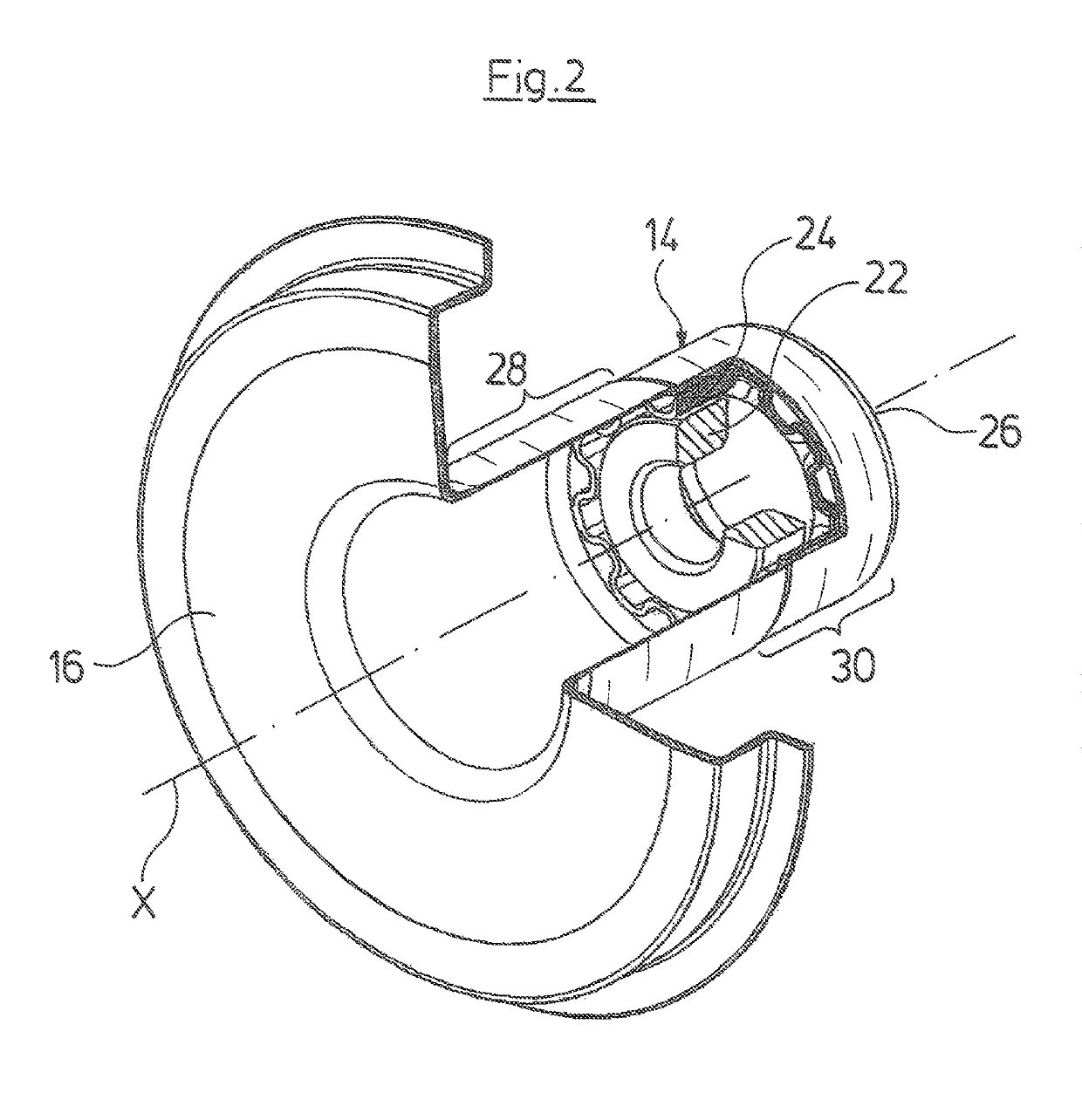
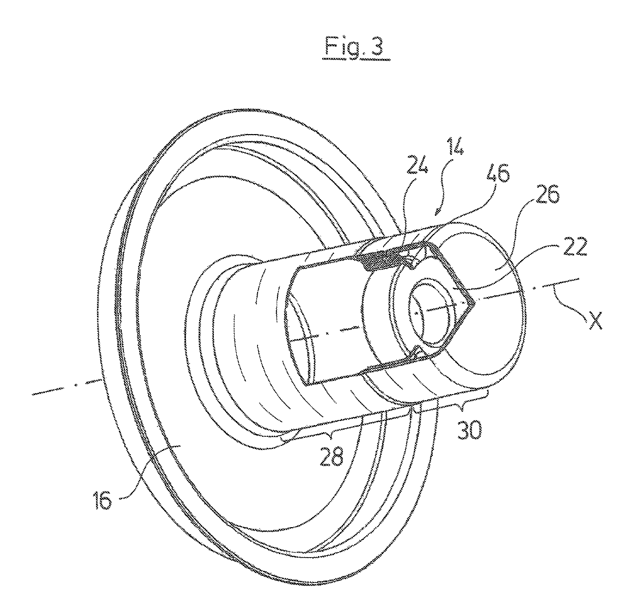
[0015]Particularly preferably, the bearing holder comprises at least one radially inwardly directed axial abutment, on which the bearing with one axial end comes into bearing contact. This abutment is preferably designed on the side of the bearing holder which faces the base of the can pot and for its part preferably bears on the base of the can pot. This abutment fixes the bearing in the axial direction and prevents the bearing from being able to slip out of the bearing holder in the axial direction or being inserted too far into the bearing holder in the axial direction.
[0016]The radially inwardly directed abutment is further preferably formed by a radially inwardly extending peripheral collar. Such a collar may be easily formed by way of deep drawing with the previously described manufacturing method, by way of the base of the beaker-like structure not being completely removed, but only a central region being removed, so that an annular section of the base as a peripheral collar remains on the inner periphery of the bearing holder.
[0020]The can pot may have a reduced wall thickness in an axial region, in which a rotor is arranged, which is to say in the axial region, in which the magnetically effective components of the rotor are arranged. By way of this, the magnetic efficiency between the stator and rotor may be improved. The bearing holder however is preferably arranged in an axial region with a non-reduced wall thickness. Thus an adequate stability of the can pot may be created in the region of the bearing, for accommodating the forces transmitted by the bearing. A thinning of the wall of the can pot may be effected by way of pressing or rolling for example. Thereby, the axial end of the can pot which faces the base of the can pot is not machined, so that this region, in which the bearing holder with the bearing is then arranged, is not thinned out. The can pot, however, over its complete axial length preferably has essentially the same diameter, with the exception of such a reduced wall thickness by thinning out the wall thickness.

Problems solved by technology

This means that the bearing holder is not designed as a solid material.

Method used


Image

  • Pump assembly
  • Pump assembly
  • Pump assembly

Examples


Embodiment Construction

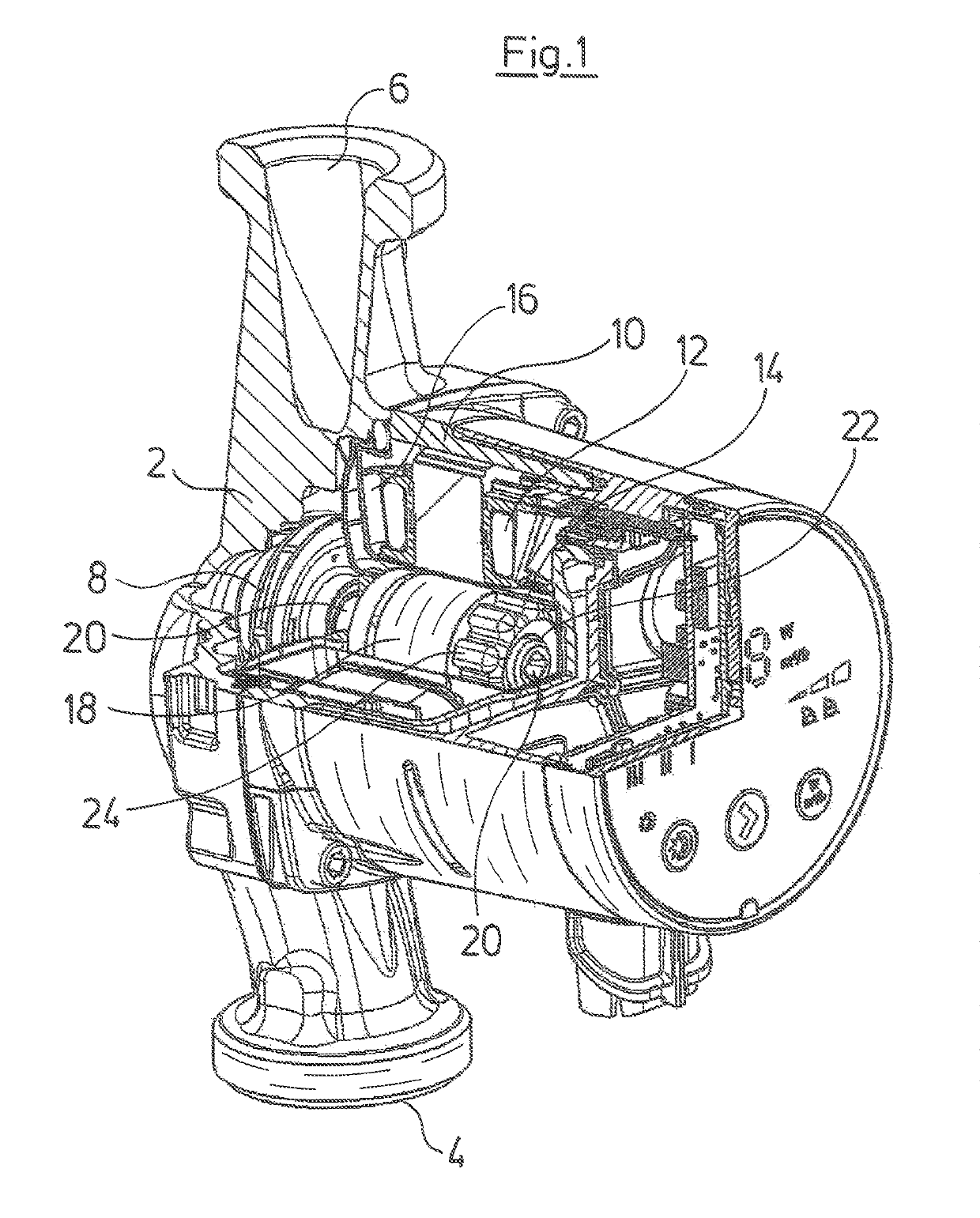
[0029]The pump assembly according to FIG. 1 is a heating circulation pump assembly which in the known manner comprises a pump housing 2 with a suction connection 4 and a pressure connection 6. An impeller 8 is arranged in the pump housing 2. A stator housing 10 with a stator 12 of an electrical drive motor which is arranged thereon, is applied onto the pump housing 2. The electric drive motor is designed as a canned motor. This means that a can pot 14 is arranged in the inside of the stator 12, said can pot via a radially outward projecting collar 16 sealing the region of the stator housing 10, in which the stator 12 is arranged, to the interior of the pump housing 2, in which the fluid to be delivered is located. A rotor 18 is arranged in the inside of the can pot 14 and rotatingly drives the impeller 8 via the motor shaft 20. The motor shaft 20 at its axial end, which is away from the impeller 8, is mounted in a radial bearing 22. The radial bearing 22 for its part is fixed in a b...


PUM


Abstract

A pump assembly has an electric drive motor which is designed as a canned motor which has a bearing (22) in the interior of motor can (14), on which a motor shaft (20) is supported. The bearing (22) has an outer diameter that is smaller than an inside diameter of the motor can (14) and the bearing (22) in the interior of the motor can (14) is supported on a bearing holder (24) which has multiple steps (40) extending traversely to an inner circumference of the motor can (14).

Description

CROSS-REFERENCE TO RELATED APPLICATIONS[0001]This application is a Section 371 of International Application No. PCT / EP2012 / 075626, filed Dec. 14, 2012, which was published in the German language on Jul. 4, 2013, under International Publication No. WO 2013 / 098099 A1 and the disclosure of which is incorporated herein by reference.BACKGROUND OF THE INVENTION[0002]The invention relates to a pump assembly having an electric drive motor designed as a canned motor, the canned motor comprising: a can pot, a bearing inside the can pot, and a motor shaft mounted in the bearing.[0003]With pump assemblies having an electric motor designed as a canned motor, such as circulation pump assemblies for heating installations, for example, a bearing is usually arranged in the inside of a can pot, in which bearing an axial end of a motor shaft is mounted in the radial direction. For fastening this bearing, it is known to weld a bearing holder onto the axial end of the can, in which bearing holder the be...

Claims


Application Information

Patent Timeline
Patent Type & Authority Patents(United States)
IPC IPC(8): F04D13/06F04D29/62F16C27/02
CPCF04D13/0633F16C27/02F04D29/628
Inventor IVERSEN, KARE
Owner GRUNDFOS HLDG
Learn More