S-shaped locking fastener structure
a technology of locking fasteners and pipes, which is applied in the direction of fastening means, securing devices, pipe supports, etc., can solve the problems of inconvenient assembly and disassembly of locking fasteners, many problems to be solved, and great defects in expandable technical links, so as to increase the friction force, enhance the fastening strength of the box body, and enhance the locking strength
- Summary
- Abstract
- Description
- Claims
- Application Information
AI Technical Summary
Benefits of technology
Problems solved by technology
Method used
Image

Examples
embodiment 1
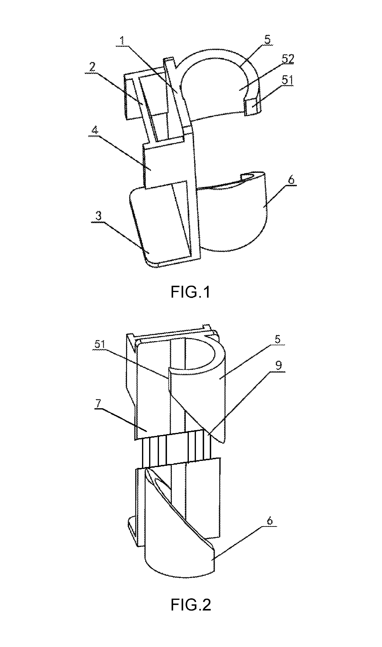
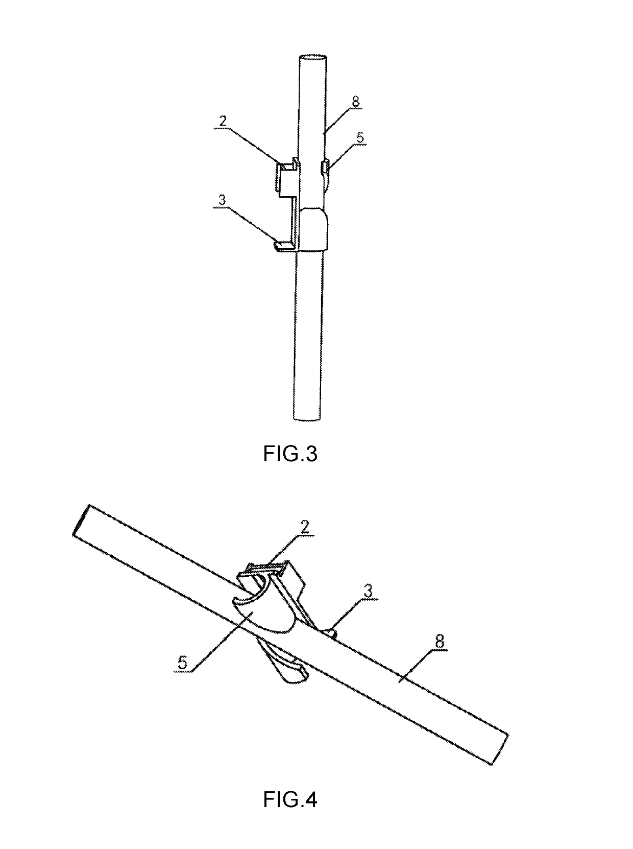
[0026]Please refer to FIGS. 1 to 4, the specific embodiment of the present invention relates to an S-shaped locking fastener structure, including a locking fastener body 1 which is provided with a vertical fastening plate 8, wherein a box fastening element which is provided with a rectangular fastening bayonet is arranged on a front side of the fastening plate 8, and a pipe locking element, which is a cylindrical locking fastener with a bevel notch, is arranged on a rear side thereof; the bevel notch divides the locking fastener into a top locking ring 5 and a bottom locking ring 6 from top to bottom, and extension rods 9, through which the length of the fastening plate 8 is adjusted, are connected in the middle of the fastening plate 8.
[0027]Further, the fastening bayonet includes an upper edge 2 and a lower edge 3, and side baffles 4 are arranged on both sides of the upper edge 2 respectively. The upper edge 2 and the two side baffles 4 form an upper bayonet structure with an I-sh...
embodiment 2
[0032]Please refer to FIGS. 1 to 4, the specific embodiment of the present invention relates to an S-shaped locking fastener structure, including a locking fastener body 1 which is provided with a vertical fastening plate 8, wherein a box fastening element which is provided with a rectangular fastening bayonet is arranged on a front side of the fastening plate 8, and a pipe locking element, which is a cylindrical locking fastener with a bevel notch, is arranged on a rear side thereof; the bevel notch divides the locking fastener into a top locking ring 5 and a bottom locking ring 6 from top to bottom, and extension rods 9, through which the length of the fastening plate 8 is adjusted, are connected in the middle of the fastening plate 8.
[0033]Specifically, a layer of bevel notch 7, which divides the locking fastener into two locking rings (i.e., the top locking ring 5 and the bottom locking ring 6) from top to bottom, is arranged in the middle of the pipe locking element, and an out...
embodiment 3
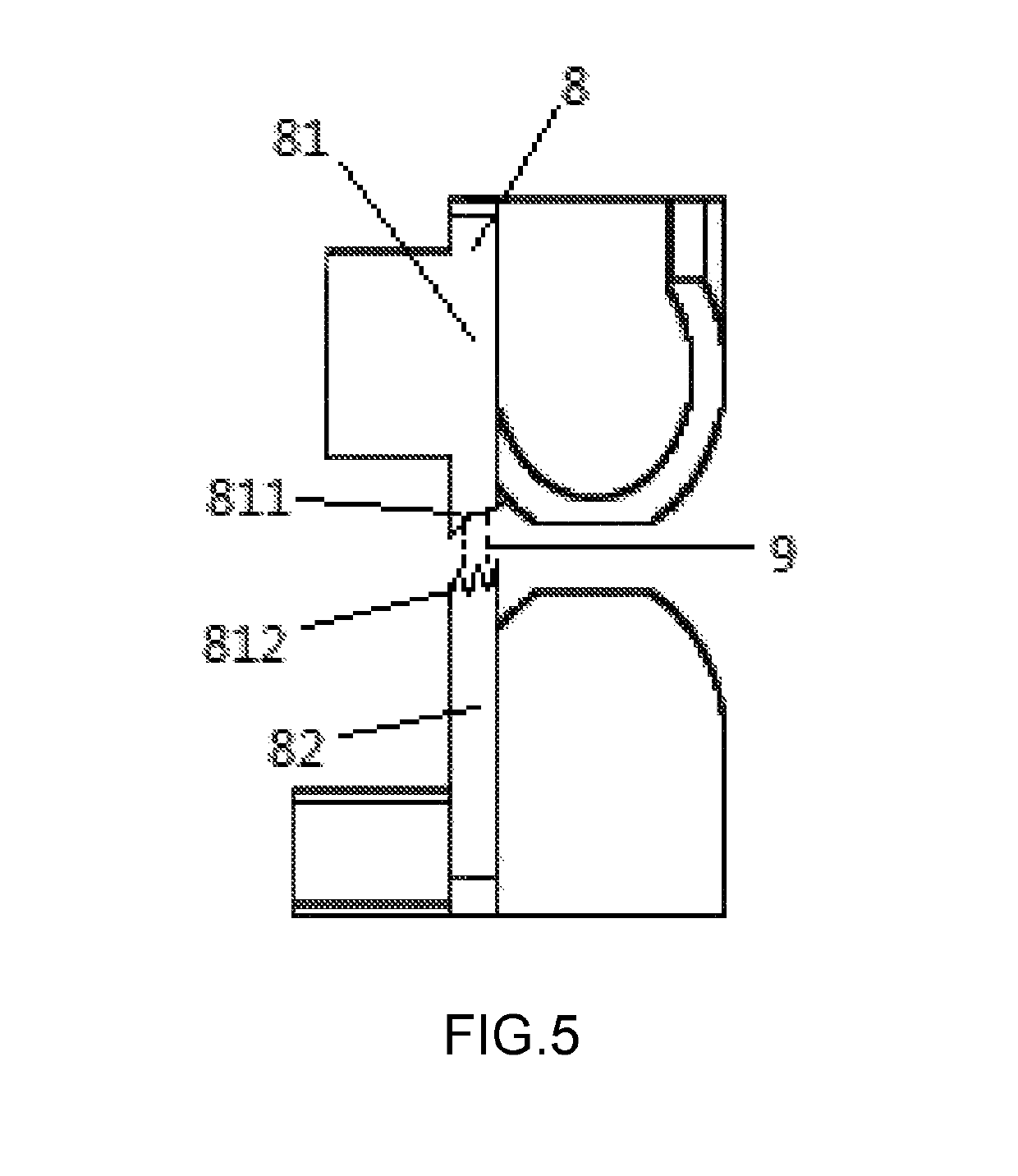
[0035]Please refer to FIGS. 1 to 5, the specific embodiment of the present invention relates to an S-shaped locking fastener structure, including a locking fastener body 1 which is provided with a vertical fastening plate 8, wherein a box fastening element is arranged on a front side of the fastening plate 8, and a pipe locking element, which is a cylindrical locking fastener with a bevel notch, is arranged on a rear side thereof; the bevel notch divides the locking fastener into a top locking ring 5 and a bottom locking ring 6 from top to bottom, and extension rods 9, through which the length of the fastening plate 8 is adjusted, are connected in the middle of the fastening plate. The box fastening element is provided with a rectangular fastening bayonet which consists of an upper edge 2 and a lower edge 3 which are tilted, wherein the tilt angle is designed into multiple angles according to the usage requirements of the box body, so that the angles for fastening the box body are d...
PUM
 Abstract
Description
Claims
Application Information
 - R&D
- Intellectual Property
- Life Sciences
- Materials
- Tech Scout
- Unparalleled Data Quality
- Higher Quality Content
- 60% Fewer Hallucinations
Browse by: Latest US Patents, China's latest patents, Technical Efficacy Thesaurus, Application Domain, Technology Topic, Popular Technical Reports.
© 2025 PatSnap. All rights reserved.Legal|Privacy policy|Modern Slavery Act Transparency Statement|Sitemap|About US| Contact US: help@patsnap.com