Glass Substrate Slicing Apparatus and Method

a glass substrate and slicing technology, applied in glass making apparatus, manufacturing tools, electric heating, etc., can solve the problems of reducing product quality, affecting the slicing accuracy of glass substrates, and affecting the slicing accuracy of diamond wheel cutters, so as to reduce horizontal cracks and the amount of glass debris, and improve the slicing accuracy

Inactive Publication Date: 2013-06-06
TCL CHINA STAR OPTOELECTRONICS TECH CO LTD
View PDF8 Cites 4 Cited by
  • Summary
  • Abstract
  • Description
  • Claims
  • Application Information

AI Technical Summary

Benefits of technology

[0018]According to the glass substrate slicing apparatus and the glass substrate slicing method of the present disclosure, a laser beam is emitted by the laser emitting device to form micro-grooves on a surface of the glass substrate so that a diamond wheel cutter slices the glass substrate at locations of the micro-grooves. As a result, the frictional force between the diamond wheel cutter and the glass substrate can be enhanced to prevent slipping of the diamond wheel cutter during the slicing process, to improve the slicing accuracy, and to reduce the horizontal cracks and the amount of glass debris generated during the slicing process. This can avoid scratching to the circuits on the glass substrate caused by the glass debris, improve the product quality and reduce the pollution caused by the glass debris to the dust-free workshop. Moreover, the abrasion between the diamond wheel cutter and the glass substrate can be reduced to prolong the service life of the diamond wheel cutter, thus reducing the production cost.

Problems solved by technology

Moreover, formation of the horizontal crack 104 causes excessive glass debris, and the glass debris will be attached to the surface of the glass substrate and the lines in a terminal region of the glass substrate to cause scratching or pollution to the surface of the glass substrate and the lines in subsequent processes, which will degrade the product quality.
Meanwhile, the flying glass debris also causes pollution to the environment in the dust-free workshop.
On the other hand, the wheel cutter suffers from a certain level of abrasion when slicing the glass substrate, and once the wheel cutter has sliced glass substrates for a certain length, the wheel cutter will fail and must be replaced with a new one.

Method used


Image

  • Glass Substrate Slicing Apparatus and Method
  • Glass Substrate Slicing Apparatus and Method
  • Glass Substrate Slicing Apparatus and Method

Examples


first embodiment

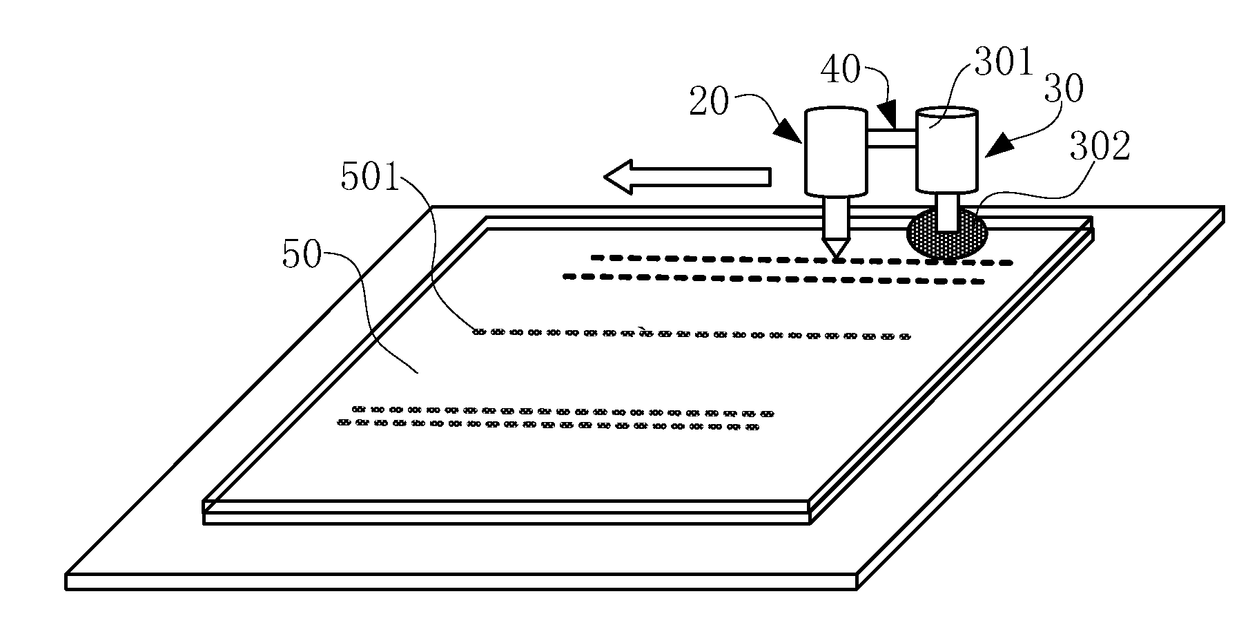
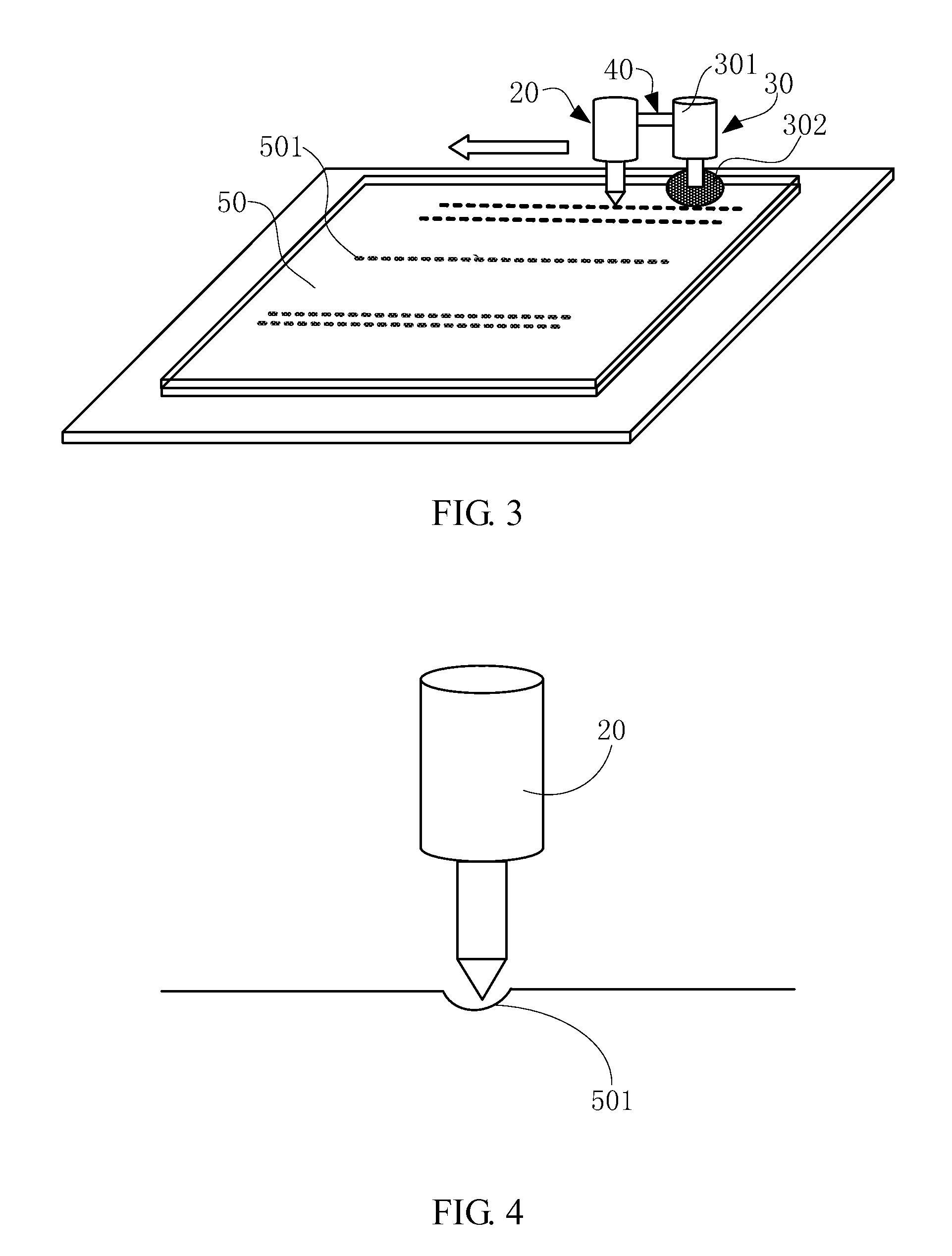
[0027]Referring to FIG. 3 to FIG. 5 together, a glass substrate slicing apparatus of the present disclosure comprises a first laser emitting device 20, a first slicing device 30 and a connecting device 40. The first laser emitting device 20 and the first slicing device 30 are disposed opposite to each other along a slicing movement direction. The connecting device 40 connects and holds the first laser emitting device 20 and the first slicing device 30. Moreover, the connecting device 40 may be fixed between the first laser emitting device 20 and the first slicing device 30, or movably connect and hold the first laser emitting device 20 and the first slicing device 30 so that relative positions of the first laser emitting device 20 and the first slicing device 30 can be adjusted.

[0028]The first laser emitting device 20 may comprise a cooling device (not shown). The first laser emitting device 20 emits a laser beam onto pre-sliced locations on a surface of a glass substrate 50 to be s...


PUM

PropertyMeasurementUnit
lengthaaaaaaaaaa
slicing movement directionaaaaaaaaaa
structureaaaaaaaaaa

Abstract

A glass substrate slicing apparatus is disclosed, which comprises a laser emitting device and a slicing device. The laser emitting device is adapted to emit a laser beam onto a surface of a glass substrate to be sliced so as to form micro-grooves on the surface of the glass substrate; and the slicing device is adapted to slice the glass substrate at locations of the micro-grooves, and comprises a wheel cutter fixing device and a diamond wheel cutter fixed on the wheel cutter fixing device. A laser beam is emitted by the laser emitting device to form micro-grooves on a surface of the glass substrate so that a diamond wheel cutter can be inserted into the micro-grooves to slice the glass substrate at locations of the micro-grooves. As a result, the frictional force between the diamond wheel cutter and the glass substrate can be enhanced to prevent slipping of the diamond wheel cutter during the slicing process, thus improving the slicing accuracy.

Description

FIELD OF THE INVENTION[0001]The present disclosure generally relates to the technical field of liquid crystal display (LCD) panels, and more particularly, to a glass substrate slicing apparatus and method.BACKGROUND OF THE INVENTION[0002]Currently, a thin film transistor liquid crystal display (TFT-LCD) panel is formed mainly by sandwiching a liquid crystal layer between an array substrate and a color film (CF) substrate through a cell process. The array substrate provides gate lines for scanning signals, signal lines for data signals and pixel electrodes. The manufacturing process of the LCD panel mainly comprises an array process for forming the array substrate and the CF substrate, a cell process for assembling the array substrate and the CF substrate together and filling a liquid crystal material therebetween, and a subsequent module process. The glass substrate comprises a plurality of LCD panels after the cell process, and the LCD panels are separated through a slicing and sin...

Claims


Application Information

Patent Timeline
Patent Type & Authority Applications(United States)
IPC IPC(8): H05B7/18
CPCC03B33/033C03B33/076B23K26/367B23K26/0093C03B33/082B23K26/364
Inventor ZHUANG, YI-ZHUANGTSAI, JUNG-MAOLIAO, SHIUE-SHIHWEN, SONG-XIANDENG, MING--FENG
Owner TCL CHINA STAR OPTOELECTRONICS TECH CO LTD
Why Eureka
Try Eureka