Pedal device for vehicles

a technology for pedal devices and vehicles, applied in mechanical control devices, process and machine control, instruments, etc., can solve the problems of increasing the size and weight wear of parts of the pedal device, so as to reduce frictional wear, reduce frictional force, and ensure the effect of reliable output valu

Active Publication Date: 2014-12-18
HYUNDAI MOTOR CO LTD +1
View PDF4 Cites 4 Cited by
  • Summary
  • Abstract
  • Description
  • Claims
  • Application Information

AI Technical Summary

Benefits of technology

This patent describes a new pedal device for vehicles that reduces the load on the hinge shaft, making it stronger and more durable. The device also reduces the size and cost of production. The pressure member in the device is separated from the pedal arm, which increases the friction and reduces wear and tear on the hinge shaft. Additionally, the device includes a pressure member that separates from the housing, resulting in less friction and hysteresis, leading to a more reliable output value from the APS. Overall, this patent describes a more robust and efficient pedal device for vehicles.

Problems solved by technology

Accordingly, the conventional accelerator pedal device for vehicles is problematic in that, to form an appropriate pedal effort of the pedal pad that is higher than a predetermined level, it is required to use a long pedal arm, and so the size of the pedal arm and the size of the pedal housing are increased, thereby increasing the size and weight of the pedal device.
Further, when the pedal pad of the conventional accelerator pedal device is pressed down, the end of the pedal aim comes into frictional contact with the inner surface of the pedal housing.
In the above state, a load generated by the pedal pad is concentrated on the bushing that surrounds the rotating shaft, and the concentration of the load causes wear of parts of the pedal device, and reduces the durability of the parts.
Further, because the hinged parts are worn due to the concentration of the load, the conventional accelerator pedal device may not produce a reliable output value of an APS.

Method used


Image

  • Pedal device for vehicles
  • Pedal device for vehicles
  • Pedal device for vehicles

Examples


Embodiment Construction

[0031]Reference will now be made in detail to various embodiments of the present invention(s), examples of which are illustrated in the accompanying drawings and described below. While the invention(s) will be described in conjunction with exemplary embodiments, it will be understood that present description is not intended to limit the invention(s) to those exemplary embodiments. On the contrary, the invention(s) is / are intended to cover not only the exemplary embodiments, but also various alternatives, modifications, equivalents and other embodiments, which may be included within the spirit and scope of the invention as defined by the appended claims.

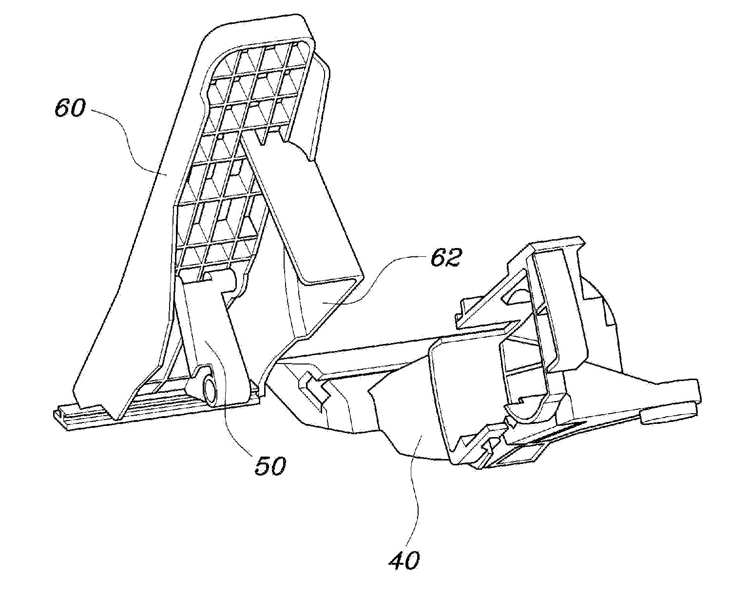
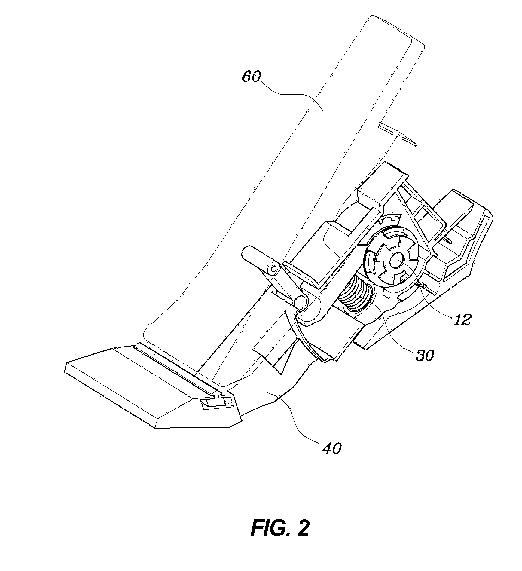
[0032]FIG. 2 is a view illustrating the construction of a pedal device for vehicles according to the present invention. FIG. 3 is a view illustrating the construction of the pedal device for vehicles according to the present invention, in which a pedal arm 10 and a pressure member 20 are combined with each other, and a carrier 50 is s...


PUM


Abstract

A pedal device for vehicles includes: a pedal arm provided in a pedal housing and connected to a pedal pad at a first end thereof, and rotated around a hinge shaft mounted to a second end of the pedal arm; a pressure member, a first end of which is held by the first end of the pedal arm, and a second end of which is placed between the hinge shaft and an inner surface of the pedal housing; and an elastic member provided between a middle portion of the pressure member and the inner surface of the pedal housing, and functioning to impose an elastic reaction force on the pressure member when a driver presses the pedal pad down. The elastic member brings the second end of the pressure member into frictional contact with the inner surface of the pedal housing.

Description

CROSS-REFERENCE TO RELATED APPLICATION[0001]The present application claims priority of Korean Patent Application Number 10-2013-0068968 filed Jun. 17, 2013, the entire contents of which application is incorporated herein for all purposes by this reference.BACKGROUND OF INVENTION[0002]1. Field of Invention[0003]The present invention relates, in general, to a pedal device for vehicles and, more particularly, to a pedal device for vehicles, which can reduce a load imposed on a hinge shaft when a pedal pad is pressed down, thereby improving the durability and wear resistance of parts, and improving the quality of an accelerator position sensor (APS), and which can be reduced in terms of the size of the device and the number of parts, thereby reducing the production cost and weight of the pedal device.[0004]2. Description of Related Art[0005]FIG. 1 illustrates a conventional organ type accelerator pedal device.[0006]As shown in FIG. 1, the conventional organ type accelerator pedal device...

Claims


Application Information

Patent Timeline
Patent Type & Authority Applications(United States)
IPC IPC(8): G05G1/44
CPCG05G1/44G05G5/03Y10T74/20528G05G1/30B60K26/02
Inventor KIM, EUN SIKKIM, BUM JUNYANG, HEE SOOMIN, JEONG SEONPARK, JOON YOUNGCHO, YANG RAECHOI, JEE HYUCKMO, YONG HWANLEE, JONG RAEKIM, DONG HWAN
Owner HYUNDAI MOTOR CO LTD
Why Eureka
Try Eureka