Drill bit for improved transport of cuttings

a technology of drilling bit and cutting edge, which is applied in the field of drill bit, can solve the problems of increasing the frictional wear of the bit and in particular the cutting edge, reducing the forward drilling rate, and reducing the cutting edge wear, so as to maximise the forward penetration rate, optimise the front face cleaning capacity, and reduce the wear of the cutting edge inser

Inactive Publication Date: 2019-07-09
SANDVIK INTELLECTUAL PROPERTY AB
View PDF13 Cites 0 Cited by
  • Summary
  • Abstract
  • Description
  • Claims
  • Application Information

AI Technical Summary

Benefits of technology

[0006]It is an objective of the present invention to provide a drill bit and in particular a percussive down-the-hole hammer (DTH) bit that is optimised for drilling efficiency and in particular for maximised penetration rate and minimised frictional wear at the bit. It is a further specific objective to provide a drill bit that is effective to facilitate the axially rearward flushing of rock debris.
[0007]The objectives are achieved by providing a drill bit having a fluid flushing passageway exiting at the axially forward cutting face of the bit head that increases the delivery of the flushing fluid to all regions and in particular the radial centre of the head. In particular, the fluid exit end of the flushing passageway at the front face is formed as an elongate slot having a length that is appreciably larger than a width.

Problems solved by technology

However, existing drill bits are disadvantageous in that certain regions of the front face do not receive the flushing fluid and are therefore susceptible to debris accumulation.
This reduces the forward drilling rate and increases the frictional wear of the bit and in particular the cutting inserts.

Method used


Image

  • Drill bit for improved transport of cuttings
  • Drill bit for improved transport of cuttings
  • Drill bit for improved transport of cuttings

Examples


Embodiment Construction

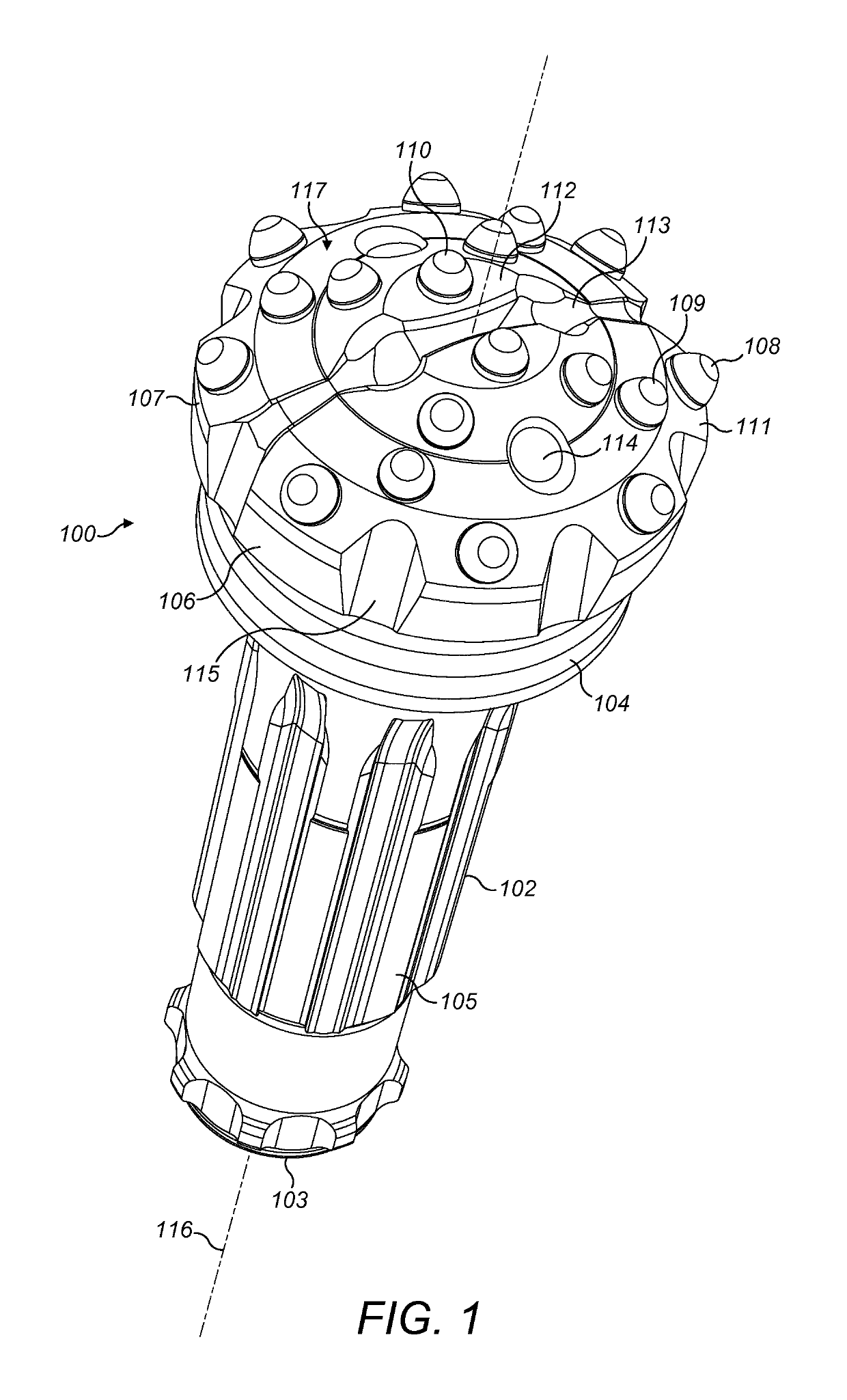
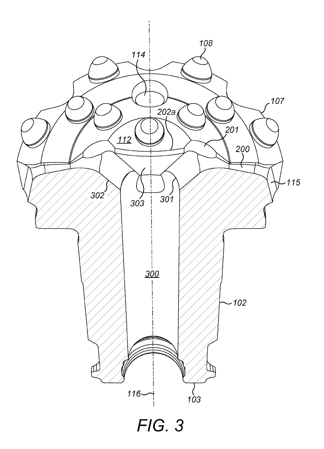
[0028]FIG. 1 is an external perspective view of a down-the-hole hammer (DTH) drill bit comprising a bit head indicated generally by reference 100 positioned at one end an elongate shank 102. Shank 102 comprises axially extending splines 105 aligned parallel to a longitudinal axis 116 of the drill bit. Head 100 is provided at a first end of shank 102 whilst a second end 103 comprises an annular rearward facing end face for contact by a reciprocated piston (not shown) within the DTH assembly. Head 100 comprises an axially rearward annular skirt 104 that provides a transition from head 100 into shank 102 with the head 100, skirt 104 and shank 102 formed integrally.

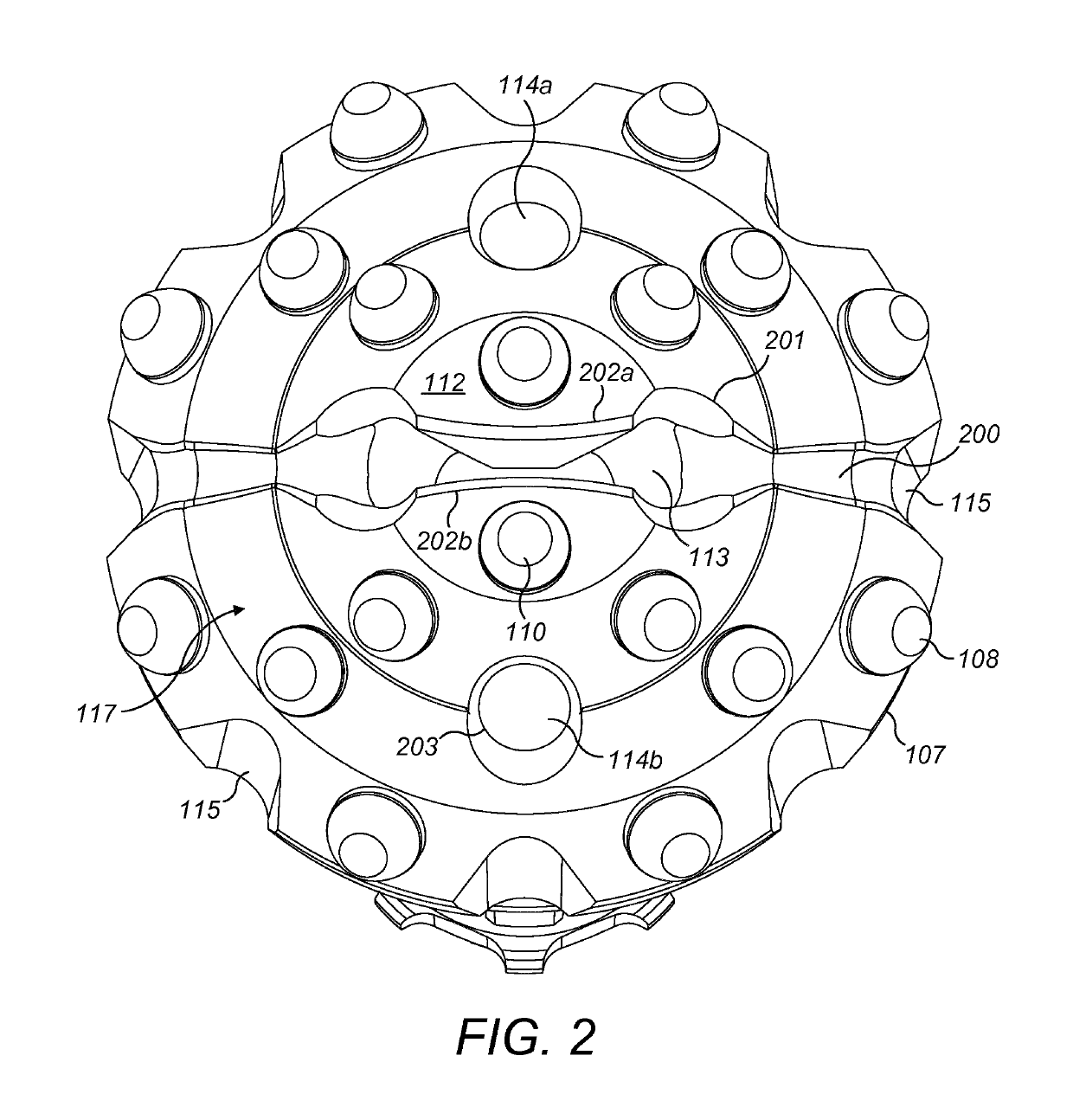
[0029]Head 100 comprises a front face indicated generally by reference 117 having a generally circular perimeter edge 107. Front face 117 is divided radially into a radially outermost gauge region 111 positioned radially closest to perimeter edge 107 and an innermost region 112 positioned radially centrally at front face 117....


PUM


Abstract

A rock drill bit includes a head provided at one end of an elongate shank. A plurality of fluid flushing passageways extend axially from an internal bore extending through the shank with at least one fluid flushing passageway having an exit end at the front face formed as an elongate slot having a length greater than a width to facilitate the rearward transport of cut rock fragment.

Description

RELATED APPLICATION DATA[0001]This application is a § 371 National Stage Application of PCT International Application No. PCT / EP2016 / 052278 filed Feb. 3, 2016 claiming priority of EP Application No. 15155777.4 filed Feb. 19, 2015.FIELD OF INVENTION[0002]The present invention relates to a drill bit and in particular, although not exclusively, to a percussive drill bit formed with a cutting head having an elongate slot at a front face of the bit for the exhaust of a flushing fluid.BACKGROUND ART[0003]Percussion drill bits are widely used both for drilling relatively shallow bores in hard rock and for creating deep boreholes. For the latter application, drill strings are typically used in which a plurality of rods are interconnected to advance the drill bit and increase the depth of the hole. In ‘top hammer drilling’ a terrestrial machine is operative to transfer a combined impact and rotary drive motion to an upper end of the drill string whilst a drill bit positioned at the lower end...

Claims


Application Information

Patent Timeline
Patent Type & Authority Patents(United States)
IPC IPC(8): E21B10/38E21B10/567
CPCE21B10/38E21B10/567
Inventor HEMPH, RASMUSKRAFT, CONNY
Owner SANDVIK INTELLECTUAL PROPERTY AB
Why Eureka
Try Eureka