Lubrication apparatus of high pressure pump for common rail system

a technology of high pressure pump and lubrication apparatus, which is applied in the direction of machines/engines, liquid fuel engines, positive displacement liquid engines, etc., can solve the problems of inferior quality of high pressure pump,/b> on which a high compression load may be severely worn by friction, etc., to prevent frictional wear of both rollers, reduce the length of passages, and improve the lubrication performance of frictional junctions

Inactive Publication Date: 2016-05-24
HYUNDAI MOTOR CO LTD
View PDF17 Cites 0 Cited by
  • Summary
  • Abstract
  • Description
  • Claims
  • Application Information

AI Technical Summary

Benefits of technology

[0014]Accordingly, the present invention has been made keeping in mind the above problems occurring in the related art, and the present invention is intended to propose a lubrication apparatus of a high pressure pump for a common rail system, which can reduce the length of a passage through which lubrication fuel flows to the frictional junction between a roller and a shoe, thereby sufficiently lubricating the frictional junction between the roller and the shoe within a short period of time, and realizing improved lubrication performance of the frictional junction, and preventing frictional wear of both the roller and the shoe, and promoting an improvement in the operational performance of the high pressure pump.
[0016]The lubrication apparatus may further include: a check valve installed in the third lubrication channel and functioning to allow a flow of fuel from the first lubrication channel to the third lubrication channel and to prevent a reverse flow of the fuel from the third lubrication channel to the first lubrication channel.
[0018]The second support groove may comprise a plurality of second support grooves that can supply a sufficient amount of fuel to the frictional junction within a predetermined short period of time.
[0024]The second support groove may comprise a plurality of second support grooves that can supply a sufficient amount of fuel to the frictional junction within a predetermined short period of time.
[0025]As described above, the lubrication apparatus of the present invention is advantageous in that it can supply a sufficient amount of lubrication fuel from the low pressure pump to the frictional junction between the roller and the shoe within a short period of time, thereby minimizing frictional wear of the frictional junction and efficiently improving the durability of the high pressure pump.

Problems solved by technology

However, the above-mentioned related art technique for lubricating the frictional junction M1 is problematic in that the passage through which the lubrication fuel flows to the frictional junction M1 between the roller 12 and the shoe 13 is too long, and so the cam shaft 21 may be operated before the frictional junction M1 between the roller 12 and the shoe 13 has been sufficiently lubricated, and, in the above state, the frictional junction M1 between the roller 12 and the shoe 13 on which a high compression load acts may be worn severely by the friction.
Furthermore, scuffing is generated in the frictional junction M1 between the roller 12 and the shoe 13, thereby causing inferiority in the quality of the high pressure pump 10.

Method used


Image

  • Lubrication apparatus of high pressure pump for common rail system
  • Lubrication apparatus of high pressure pump for common rail system
  • Lubrication apparatus of high pressure pump for common rail system

Examples


Embodiment Construction

[0029]Reference will now be made in detail to various embodiments of the present invention(s), examples of which are illustrated in the accompanying drawings and described below. While the invention(s) will be described in conjunction with exemplary embodiments, it will be understood that present description is not intended to limit the invention(s) to those exemplary embodiments. On the contrary, the invention(s) is / are intended to cover not only the exemplary embodiments, but also various alternatives, modifications, equivalents and other embodiments, which may be included within the spirit and scope of the invention as defined by the appended claims.

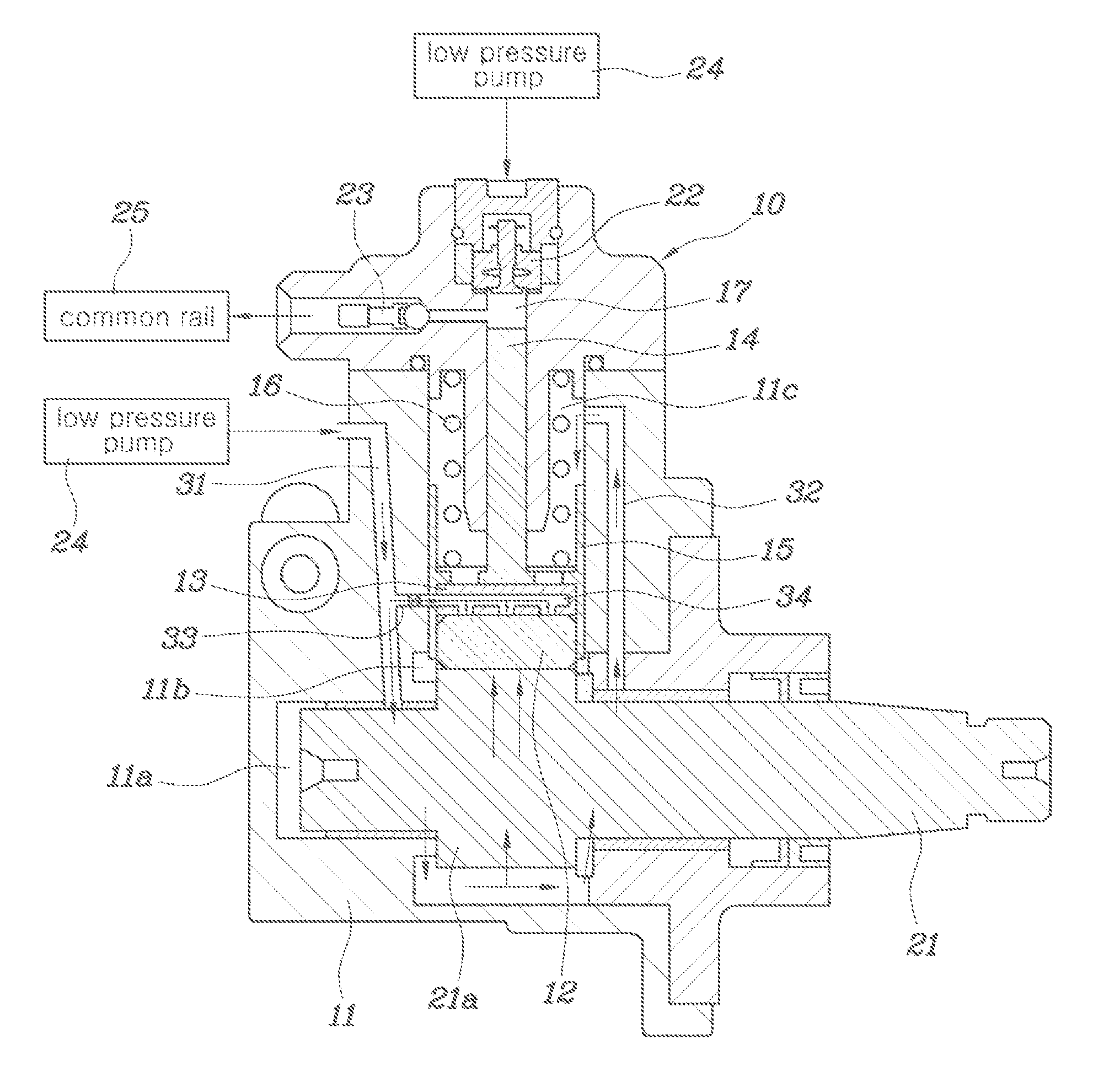
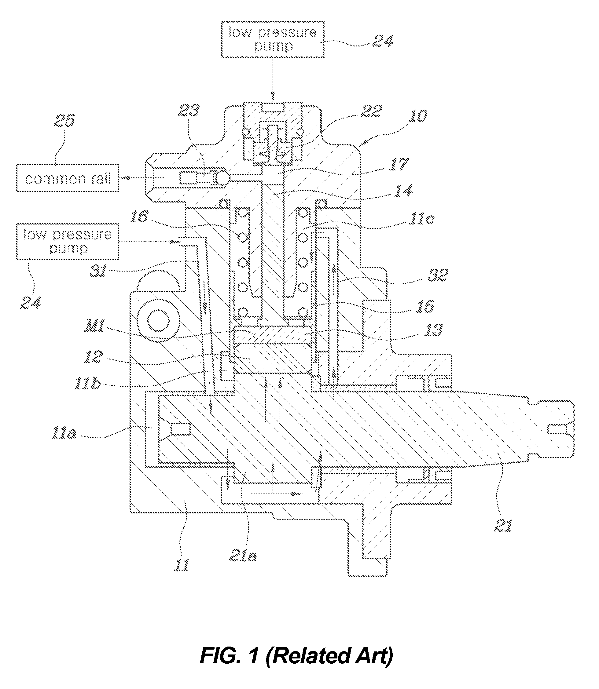
[0030]As shown in FIGS. 3 through 6, the present invention provides a high pressure pump 10 for a common rail system, which includes a pump housing 11, a roller 12, a shoe 13 and a plunger 14, with a shaft chamber 11a, a roller chamber 11b and a spring chamber 11c formed in the pump housing 11 in such a way that the chambers 11a, 11b ...


PUM


Abstract

A lubrication apparatus of a high pressure pump for a common rail system is configured such that a sufficient amount of lubrication fuel can be supplied from a low pressure pump to the frictional junction between a roller and a shoe within a short period of time, thereby efficiently improving the lubrication performance of the frictional junction.

Description

CROSS REFERENCE TO RELATED APPLICATION[0001]The present application claims priority of Korean Patent Application Number 10-2013-0073403 filed Jun. 26, 2013, the entire contents of which application is incorporated herein for all purposes by this reference.BACKGROUND OF INVENTION[0002]1. Field of Invention[0003]The present invention relates to a lubrication apparatus of a high pressure pump for a common rail system and, more particularly, to a lubrication apparatus of a high pressure pump for a common rail system which is configured such that it can realize improved lubrication performance of a frictional junction in which a roller and a shoe come into contact with each other.[0004]2. Description of Related Art[0005]Generally, as shown in FIGS. 1 and 2, a high pressure pump 10 used in a common rail system includes a pump housing 11, a roller 12, a shoe 13, and a plunger 14. Here, in the pump housing 11, a shaft chamber 11a, a roller chamber 11b and a spring chamber 11c are formed in ...

Claims


Application Information

Patent Timeline
Patent Type & Authority Patents(United States)
IPC IPC(8): F04B53/18F04B49/22F04B1/04
CPCF04B53/18F04B1/0408F04B1/0413F02M59/102F02M63/0001F01M1/16F02M59/00F02M59/44F04D29/06
Inventor KWUN, SUN DONGYOU, SUNG ILHWANG, CHANG SUN
Owner HYUNDAI MOTOR CO LTD
Why Eureka
Try Eureka