Pipe joint having releasably engageable plug and socket

a plug and socket, releasable technology, applied in the direction of couplings, container discharging methods, vessel construction details, etc., can solve the problems of high leakage risk, complicated structure of pipe joints, and increase in the number of connecting parts

Active Publication Date: 2019-04-30
TOKYO TATSUNO CO LTD
View PDF4 Cites 4 Cited by
  • Summary
  • Abstract
  • Description
  • Claims
  • Application Information

AI Technical Summary

Benefits of technology

[0011]The present invention has been made in consideration of the above problems in the prior art, and the object thereof is to provide a pipe joint for emergency releasing with a minimized seal structure to minimize leakage risk.
[0016]With the pipe joints (100, 101) with the above construction, since central axes of the passages (1A, 21A) of the plug (10) and the socket (20) do not form a straight line (for example, the central axes are orthogonal), central axes of the valve rod (2) of the plug (10) and the valve rod (22) of the socket (20) do not form a straight line also, and both end portions of the valve rod (2) of the plug (10) and the valve rod (22) of the socket (20) are not contacted with each other in a straight line, and the both end portions are not pressed with each other. Therefore, even when high pressure hydrogen gas is fed, forces that both end portions of the valve rods (22, 2) are pressed with each other do not increase, and the socket (20) and the plug (10) are not separated from each other. Then, the both end portions of the rods (22, 2) are not pressed with each other, separating directions of the socket (20) and the plug (10) are not aligned with each other, so that the separated socket (20) and plug (10) are not blown off. Further, the pipe joints (100, 101) can be decreased in size and weight. In addition, handleability of the filling hose at filling of high pressure hydrogen gas improves, for instance.
[0019]In the present invention, when on one end of a socket side valve rod (22) with at least one opening (22A) is mounted (a valve element 25 of) a socket side shutoff valve (24) against an elastic body (23: socket side spring), and another end of the socket side valve rod (22) contacts a case (3) for accommodating a plug side valve rod (2) of a plug (10), when the plug (10) and the socket (20) are separated from each other, it is prevented that a high pressure hydrogen gas leaks from a side that the socket (20) is connected through the socket side shutoff valve (24) (basically apparatus side, possibly vehicle side).
[0020]Or, in the present invention, when on one end of a plug side valve rod (2) is mounted (a valve element 6 of) a plug side shutoff valve (5) against an elastic body (4: plug side spring), and another end is locked by at least one locking member (7: locking ball) to open the plug side shutoff valve (5), when the plug (10) and the socket (20) are separated from each other, it is prevented that a high pressure hydrogen gas leaks from a side that the plug (10) is connected through the shutoff valve (5) (basically vehicle side, possibly filling apparatus side).

Problems solved by technology

But, there is a problem that mounting these seal materials 336, 316, 338 and 318 makes structure of the pipe joint 300 complicated to increase the number of parts.
But, in the conventional technique, a coupling 11 for emergency releasing and a filling apparatus 1 are connected through a hose 4A with each other, and both end portions of the hose 4A become connecting portions, so that this conventional technique has a problem that the number of connecting portions increases to make leakage risk high.

Method used


Image

  • Pipe joint having releasably engageable plug and socket
  • Pipe joint having releasably engageable plug and socket
  • Pipe joint having releasably engageable plug and socket

Examples


Embodiment Construction

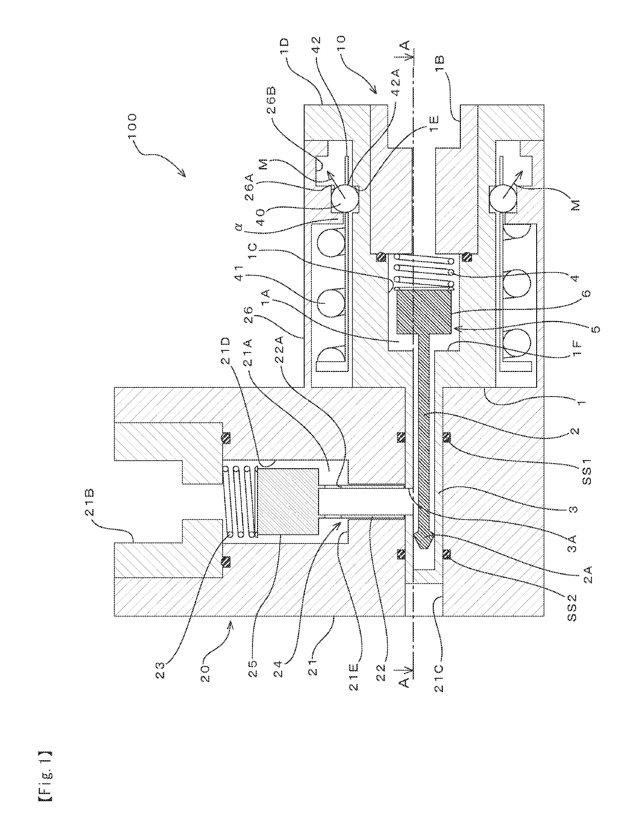
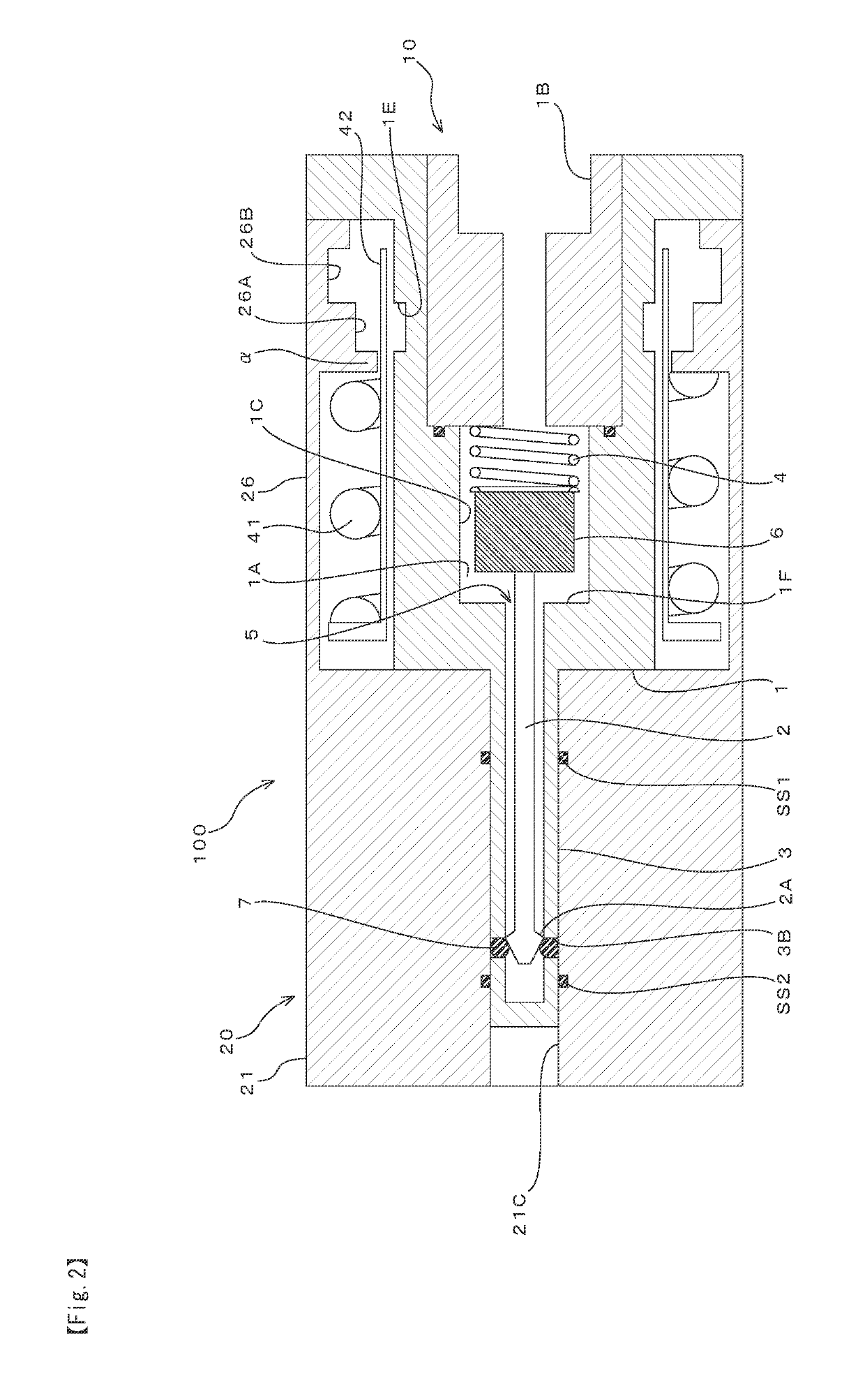
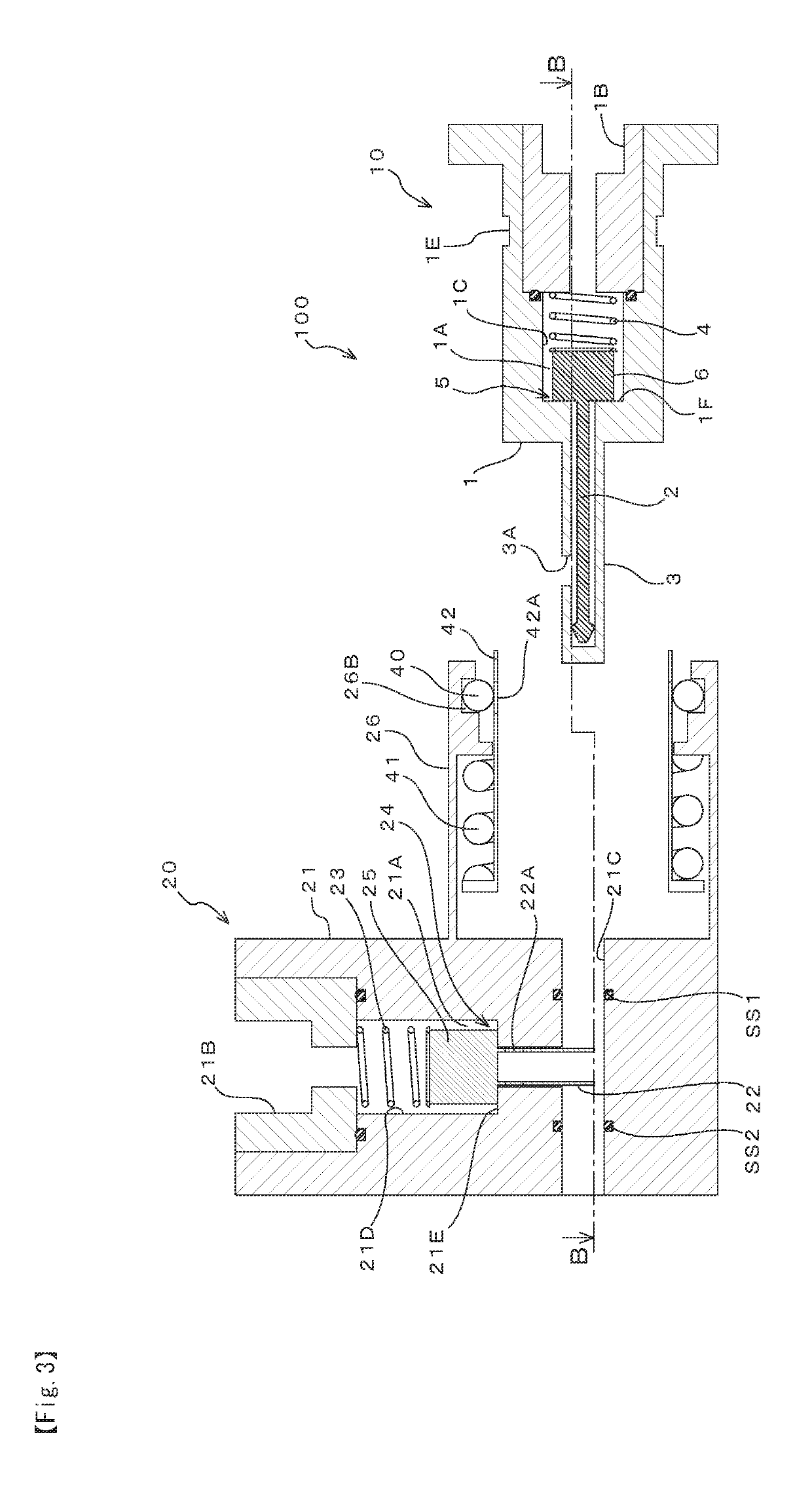
[0032]Hereinafter, embodiments of the present invention will be explained with reference to the attached drawings. At first, the first embodiment of the present invention will be explained with reference to FIGS. 1 to 4. A pipe joint 100 (pipe joint for emergency releasing) includes a plug 10 and a socket 20. FIGS. 1 and 2 show a condition that the plug 10 and the socket 20 are connected with each other. Here, the plug 10 is basically arranged on a vehicle side, and the socket 20 is basically connected on a hydrogen filling apparatus (or a dispenser) side. Meanwhile, it is possible to arrange the plug 10 on a hydrogen filling apparatus (or a dispenser) side and to arrange the socket 20 on a vehicle side.

[0033]In FIG. 1, the plug 10 shaped like a cylinder as a whole body includes a plug main body 1 and a plug side rod case 3. To a central portion (a vertically central portion at a right end of the plug main body 1 in FIG. 1) on the vehicle side (right side in FIG. 1, a side apart fro...


PUM


Abstract

To provide a pipe joint for emergency releasing with a minimized seal structure to minimize leakage risk. Pipe joints (100, 101: pipe joints for emergency releasing) of the present invention include a cylindrical plug (10) in which a passage (1A: in-plug passage) is formed, a cylindrical socket (20) in which a passage (21A: in-socket passage) is formed, and shutoff valves (5, 24) mounted in the plug (10) and the socket (20) for opening the passages (1A, 21A) of the plug (10) and the socket (20) when the plug (10) is inserted into the socket (20) and shutting the passages (1A, 21A) of the plug (10) and the socket (20) when the plug (10) detached from the socket (20), wherein central axes of the passages (1A, 21A) of the plug (10) and the socket (20) do not form a straight line.

Description

CROSS-REFERENCE TO RELATED APPLICATIONS[0001]The present application claims priority to Japanese Patent Application No. 2016-240235 filed on Dec. 12, 2016, the disclosure of which is incorporated herein by reference.STATEMENT RE: FEDERALLY SPONSORED RESEARCH / DEVELOPMENT[0002]Not ApplicableBACKGROUND1. Field of the Invention[0003]The present invention relates to a filling apparatus for filling gas such as hydrogen gas used as fuel. More particularly, the present invention relates to a pipe joint for separating a filling hose and the filling apparatus from each other in an emergency.2. Description of the Related Art[0004]For example, to a vehicle A using hydrogen as fuel, as show in FIG. 9, at a hydrogen filling station is filled hydrogen gas after a filling nozzle 202 mounted on an end of a filling hose 201 and a vehicle side filling port 203 are connected with each other. The filling is performed while being controlled depending on the maximum using pressure of a hydrogen tank 204 m...

Claims


Application Information

Patent Timeline
Patent Type & Authority Patents(United States)
IPC IPC(8): F16L29/04F16L55/10F16L37/35F16L37/23F16L27/06F17C13/00
CPCF16L29/04F16L27/06F16L37/23F16L55/1015F16L37/35F17C2250/0478F17C13/00F17C2205/037F17C6/00F17C2221/012F17C2223/0123F17C2223/036F17C2225/0123F17C2225/036F17C2260/036F17C2265/065F17C2270/0168Y02E60/32
Inventor TAKEZAWA, MASAHIROTERASOMA, YUKIKIMURA, KIYOSHI
Owner TOKYO TATSUNO CO LTD
Why Eureka
Try Eureka