Mini light machine systems

a technology of light machine and light fixture, which is applied in the field of tools, can solve problems such as the challenge of hanging lights from windows

Active Publication Date: 2019-04-30
FRANCESCHINA KAREN SUE
View PDF10 Cites 0 Cited by
  • Summary
  • Abstract
  • Description
  • Claims
  • Application Information

AI Technical Summary

Benefits of technology

[0006]A mini light machine system is disclosed herein, in a preferred embodiment, comprising a mini light machine assembly further comprising a placing machine and a light box container. In the preferred embodiment, the placing machine adheres to a window and automatically dispenses a light strand that is bonded to the window in a uniform fashion with easy peel tape that sticks the light strand to the window. Easy peel tape offers the advantage of easy removal of the light strand. The placing machine and said light box container are structured and arranged together in combination for providing a means by which to uniformly place a strand of lights along a window frame and adhere the strand of lights to a window with the easy peel tape.
[0007]The placing machine further comprises at least two first coupling mechanisms and a first power connection for connecting to the light box container. The placing machine is self-propelled by an electrically powered assembly in combination with a drive assembly comprised of at least three wide alignment wheels thus providing the advantage of uniformly placing a light strand along a window. Automated self-propelled operation offers a further advantage of accessing places that are difficult to reach. Additionally, a window wiper assembly cleans the window for improved adherence of the mini light machine assembly as well as the easy peel tape. The placing machine includes a handle for adhering and removing the mini light machine assembly. The light strand is placed by a light strand dispensing mechanism that is internal to the placing machine while automatically adhering a light strand using a tape dispensing assembly and a tape placement assembly. Both the placing machine and light box container are powered by a power source that is connected to the electrical assembly with a switch. A roll of easy peel tape is secured in the placing machine with a mounting fixture. The placing machine includes a light strand entrance aperture for a light strand to enter the device and a combination light strand and tape placement aperture so a light strand can exit the device for uniform placement along a window as well as adhering the light strand to the window. The placing machine also has a catcher pocket for storing spent backing from the easy peel tape.
[0009]The preferred embodiment includes a light box container that comprises at least two second coupling mechanisms and a second a power connection. The light box container is removably coupleable to the placing machine. The light box container includes a light strand exit aperture as an exit point for a light strand. The light box container has a flip down door and a light box lid in order to access an inner volume for loading a light strand. The light box container further comprises a guide assembly and light tray. The guide assembly comprises a plurality of guides that further comprise a tension release lever, a plurality of light strand clips, and a movable clip track that provide the advantage of loading and retaining light strands in a condensed fashion. The light tray comprises an inner volume and a plastic slip cover for further retaining light strands. The flip down door enables the plurality of light guides to slide out of the light box container in a drawer like fashion for ease of loading a light strand. Certain embodiments may not have a light box.
[0010]The electrically powered assembly comprises intelligence for propelling the mini light machine assembly around the interior of a window frame. The intelligence and a position sensor work together in functional combination for detecting the end of a window frame and gathering data as to the distance covered and length of light strand dispersed. The intelligence is further used for establishing the placement distance between individual lights along a light strand as well as providing a means for accommodating plugs on multiple light strands. The intelligence works in conjunction with the guide assembly to automatically adjust the light strand spacing to accommodate for the presence of plugs in multiple light strands thus providing the advantage of an evenly place light strand. The plurality of light strand clips are a means for aligning the light strand for dispersing through the light strand exit aperture. The dual purpose tension release lever provides a means to compress the plurality of light strand clips when in one position while providing a means to guide a light strand when in a second position.

Problems solved by technology

Hanging lights from windows can pose a challenge in terms of adherence methods as well as for accessibility especially for the elderly and those with limited movement.

Method used


Image

  • Mini light machine systems
  • Mini light machine systems
  • Mini light machine systems

Examples


Embodiment Construction

[0020]Preferably, a mini light machine system should provide means to uniformly place and adhere a light strand to a window and, yet would operate reliably and be manufactured at a modest expense. Thus, a need exists for a reliable mini light machine system to avoid the above-mentioned problems.

[0021]As discussed above, embodiments of the present invention relate to tools and more particularly to a mini light machine system as used to improve the ability to uniformly adhere a light strand to a window.

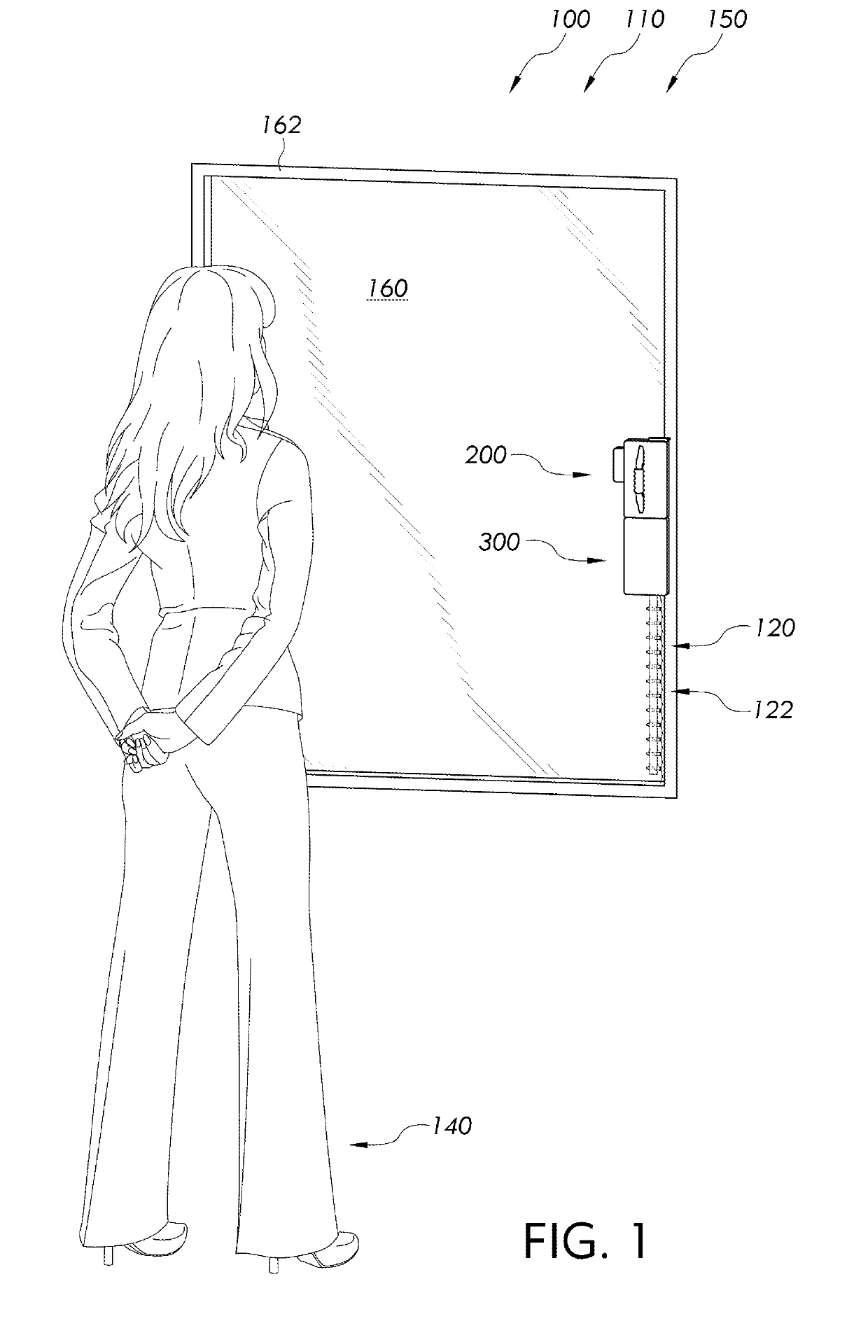
[0022]Generally speaking, a mini light machine system may comprise a mini light machine assembly further comprising a placing machine and a light box container. Mini light machine system is structured and arranged to provide a means by which to evenly place a light strand along a window while using a window frame as a guide, and applying easy peel tape for adherence of the light strand to the window.

[0023]Referring to the drawings by numerals of reference, there is shown in FIG. 1, mini...


PUM


Abstract

A mini light machine system for evenly distributing a light strand along a window frame and adhering the light strand to a window with easy peel tape. The mini light machine system has a mini light machine assembly. The mini light machine assembly has a placing machine for placing and adhering a light strand and a light box container for condensed loading and storage of a light strand. In the preferred embodiment the mini light machine assembly is self-propelled and automatically places a light strand in repeatable distances between the individual lights. The mini light machine assembly adheres to a vertical window surface allowing lights to be placed in hard to reach places. Intelligent control is used to cease operation when the mini light machine assembly reaches the end of a window frame. The mini light machine assembly contains a battery thus eliminating the need for power chords.

Description

BACKGROUND OF THE INVENTION[0001]The following includes information that may be useful in understanding the present invention(s). It is not an admission that any of the information provided herein is prior art, or material, to the presently described or claimed inventions, or that any publication or document that is specifically or implicitly referenced is prior art.1. Field of the Invention[0002]The present invention relates generally to the field of tools and more specifically relates to auxiliary devices for hanging lights.2. Description of Related Art[0003]Displaying decorative lights is a manner by which to celebrate various occurrences and holidays. Decorative lights are often hung in windows for both internal and external viewing. It is desirable to hang light strands in a secure and uniform manner with the ability to easily remove them. Hanging lights from windows can pose a challenge in terms of adherence methods as well as for accessibility especially for the elderly and t...

Claims


Application Information

Patent Timeline
Patent Type & Authority Patents(United States)
IPC IPC(8): F21S4/10H01J9/00F21W121/00
CPCF21S4/10H01J9/00F21W2121/00
Inventor FRANCESCHINA, KAREN SUE
Owner FRANCESCHINA KAREN SUE
Why Eureka
Try Eureka