Distance measuring device and solid-state image sensor used therein

a technology of distance measurement and solid-state image sensor, which is applied in the direction of distance measurement, instruments, surveying and navigation, etc., can solve the problems measurement distance, and impairing measurement precision, and achieve the effect of easy detection of interferen

Active Publication Date: 2019-05-07
PANASONIC SEMICON SOLUTIONS CO LTD
View PDF7 Cites 0 Cited by
  • Summary
  • Abstract
  • Description
  • Claims
  • Application Information

AI Technical Summary

Benefits of technology

[0013]Accordingly, when there exists interference, the difference between the first-time exposure amount and the second-time exposure amount with the particular exposure signal is enhanced, whereby interference detection is facilitated.
[0015]Accordingly, an excessively small exposure amount and an excessively great exposure amount are excluded from the comparison target, thereby avoiding the influence of shot noise.
[0019]Accordingly, it is determined that interference exists when the number of the pixels with possible interference is greater than a predetermined number. Thus, determination precision can be improved.
[0021]Accordingly, it is determined that interference exists when the number of the pixels with possible interference is greater than the predetermined number and successive. Thus, determination precision can be improved.
[0023]Accordingly, in the case where other distance measuring device of the same type operates nearby also, interference can be easily detected.

Problems solved by technology

In measuring a distance according to this scheme (hereinafter referred to as the TOF scheme), presence of other TOF distance measuring system within the measurement range causes interference of projected light pulses, which results in an error in the measured distance, impairing the measurement precision.
Accordingly, in the case where other distance measuring device of the same type operates nearby also, interference can be easily detected.

Method used


Image

  • Distance measuring device and solid-state image sensor used therein
  • Distance measuring device and solid-state image sensor used therein
  • Distance measuring device and solid-state image sensor used therein

Examples


first exemplary embodiment

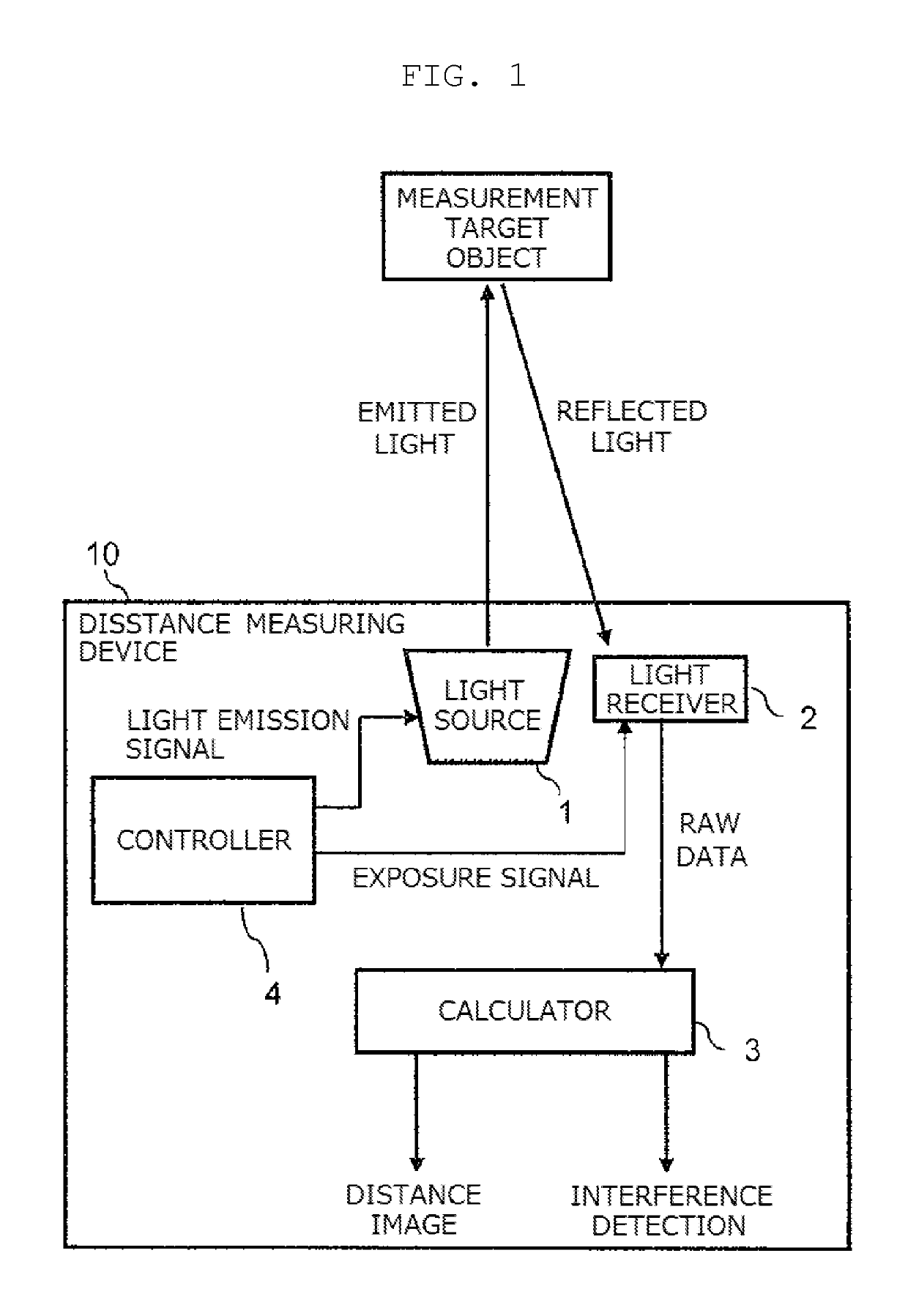
[0045]FIG. 1 is a block diagram showing an exemplary configuration of a distance measuring device (a distance measuring and imaging device) according to first exemplary embodiment.

[0046]Distance measuring device 10 is configured by light source 1, light receiver (solid-state image sensor) 2, calculator (TOF calculator) 3, and controller 4.

[0047]Firstly, a description will be briefly given of the basic TOF operation principle of distance measuring device 10 according to the present exemplary embodiment.

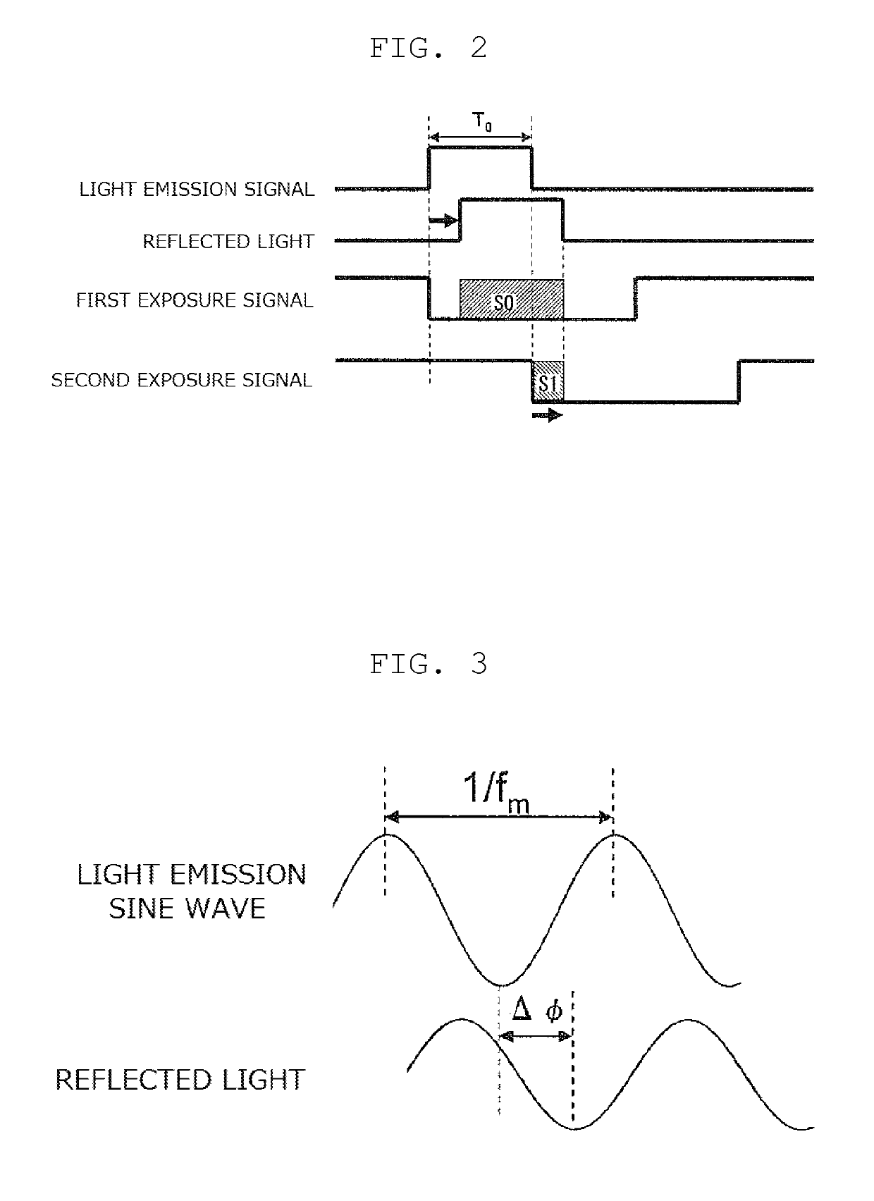
[0048]FIG. 2 is a timing chart showing a light emission signal and exposure signals in the TOF scheme. In FIG. 2, for the sake of convenience, what are shown in parallel are two patterns which originally differ from each other in timing, namely, the pattern in which exposure is performed with a first exposure signal (which is referred to as first exposure) and the pattern in which exposure is performed with a second exposure signal (which is referred to as second exposure). In the TOF ...

second exemplary embodiment

[0101]In the following, with reference to the drawings, a description will be given of the configuration and operation of a distance measuring device (a distance measuring and imaging device) according to second exemplary embodiment, focusing on the difference from the first exemplary embodiment.

[0102]The second exemplary embodiment is characterized in the exposure method performed by a light receiver (a solid-state image sensor), in which measurement is performed with different light emission and exposure conditions between even lines and odd lines. This can expand the dynamic range.

[0103]FIG. 14 is a view showing an array of pixels of a solid-state image sensor being a light receiver.

[0104]The solid-state image sensor includes a plurality of pixels that receive light. The solid-state image sensor time-divisionally performs capturing for measuring a distance under different conditions between even lines and odd lines. The solid-state image sensor transfers images obtained from the ...


PUM


Abstract

A distance measuring device using a TOF (Time of Flight) scheme includes a controller, a light receiver, and a calculator. The controller generates a first exposure signal, a second exposure signal, a third exposure signal, and one particular exposure signal selected from the first, the second, and the third exposure signals. The light receiver performs a first exposing process, a second exposing process, a third exposing process, and a particular exposing process corresponding to the particular exposure signal out of the first, the second, and the third exposing processes. The calculator determines, based on a difference between an exposure amount obtained from the particular exposing process and an exposure amount obtained from an exposing process according to one of the first, second, and the third exposure signals corresponding to the particular exposure signal, whether or not the light emitted from the distance measuring device interferes with light emitted from other distance measuring device.

Description

RELATED APPLICATIONS[0001]This application is a Continuation of International Application No. PCT / JP2015 / 000384, filed on Jan. 29, 2015, which in turn claims priority from Japanese Patent Application No. 2014-119128, filed on Jun. 9, 2014, the contents of all of which are incorporated herein by reference in their entireties.BACKGROUND[0002]1. Technical Field[0003]The present disclosure relates to a distance measuring device.[0004]2. Description of the Related Art[0005]There exists a scheme which enables three-dimensional measurement utilizing distance dependence of time of flight (TOF) of a light pulse, which time of flight is from transmission of a light pulse to reception of the light pulse reflected and returning from an object. In measuring a distance according to this scheme (hereinafter referred to as the TOF scheme), presence of other TOF distance measuring system within the measurement range causes interference of projected light pulses, which results in an error in the meas...

Claims


Application Information

Patent Timeline
Patent Type & Authority Patents(United States)
IPC IPC(8): G01C3/08G01C3/06G01S7/487G01S17/89G01S17/10G01S7/486G01S7/4865G01S17/894
CPCG01S7/4865G01C3/06G01S17/89G01S7/4876G01S17/10G01C3/085G01S17/894
Inventor TAKAHASHI, SYOMATAKANO, HARUKAKANEMITSU, TOMOHIKO
Owner PANASONIC SEMICON SOLUTIONS CO LTD
Why Eureka
Try Eureka