
Detecting method for blood

a detection method and blood technology, applied in the field of biological sample detection methods, can solve the problems of large size, difficult miniaturization, time-consuming, centrifugation method, etc., and achieve the effects of reducing interference to blood cells, low detection limit, and high sensitivity

Active Publication Date: 2021-01-05
NATIONAL TSING HUA UNIVERSITY
View PDF26 Cites 0 Cited by
  • Summary
  • Abstract
  • Description
  • Claims
  • Application Information

AI Technical Summary

Benefits of technology

The invention provides a method for detecting blood that has a low detection limit and high sensitivity and can use whole blood for detection while reducing interference to the blood cells. The method uses a special technique to generate voltage difference and capacitance effects to detect the target molecule in high salt concentration. This method has a gain effect and can detect subtle electrical signals.

Problems solved by technology

However, the centrifugation method has disadvantages such as large size, difficult miniaturization, time consuming, and high cost.
The filtering method is time consuming.
The fluid mechanics method causes difficult miniaturization and increases process difficulty.

Method used


Image

  • Detecting method for blood
  • Detecting method for blood
  • Detecting method for blood

Examples


experimental example 1

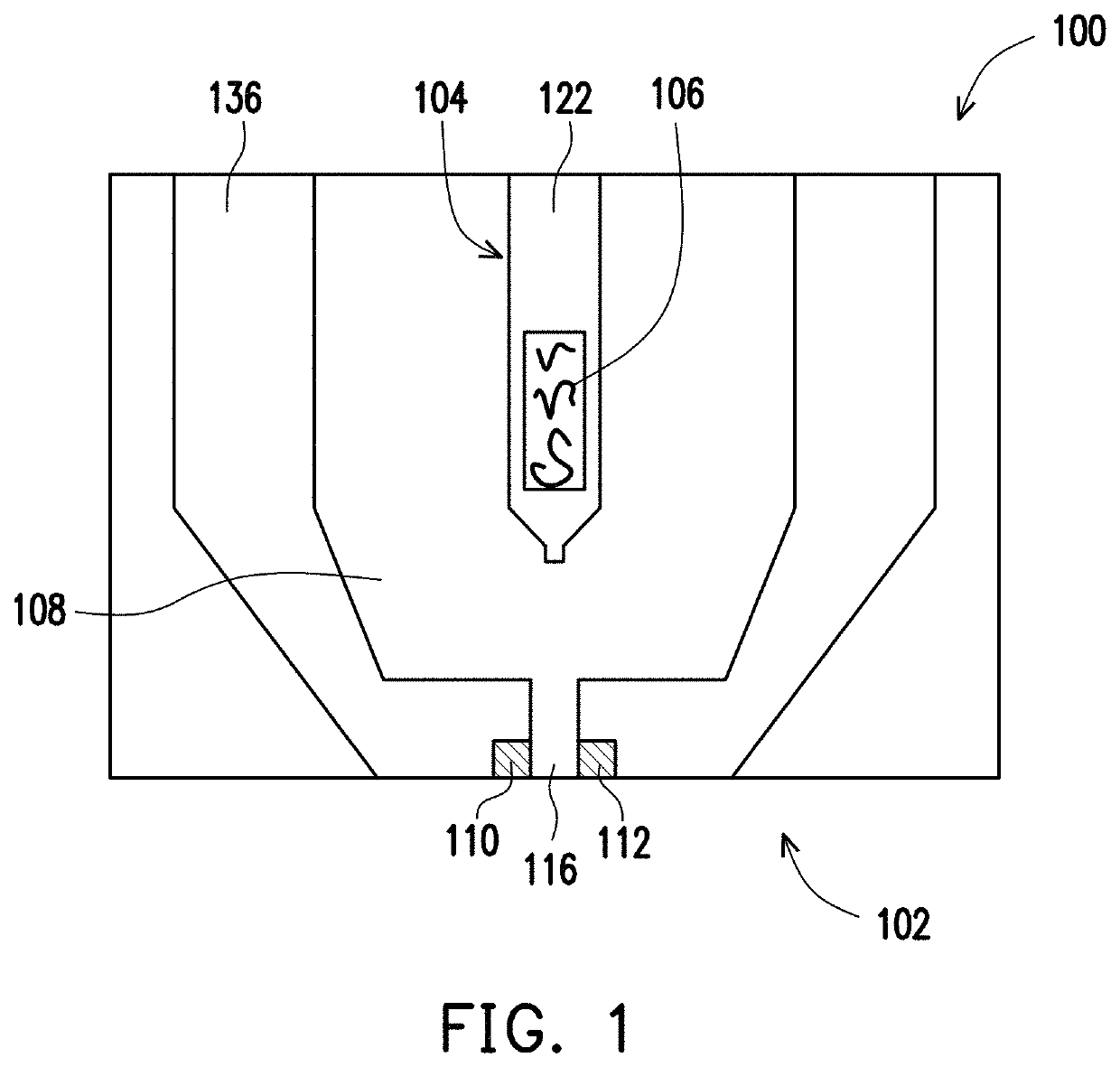
[0061]In experimental example 1, the sensing device 100 shown in FIG. 1 is used for the test. After human whole blood was added dropwise to the response electrode of the sensing device, the sensing device was inverted and current variation at different times was detected.

experimental example 2

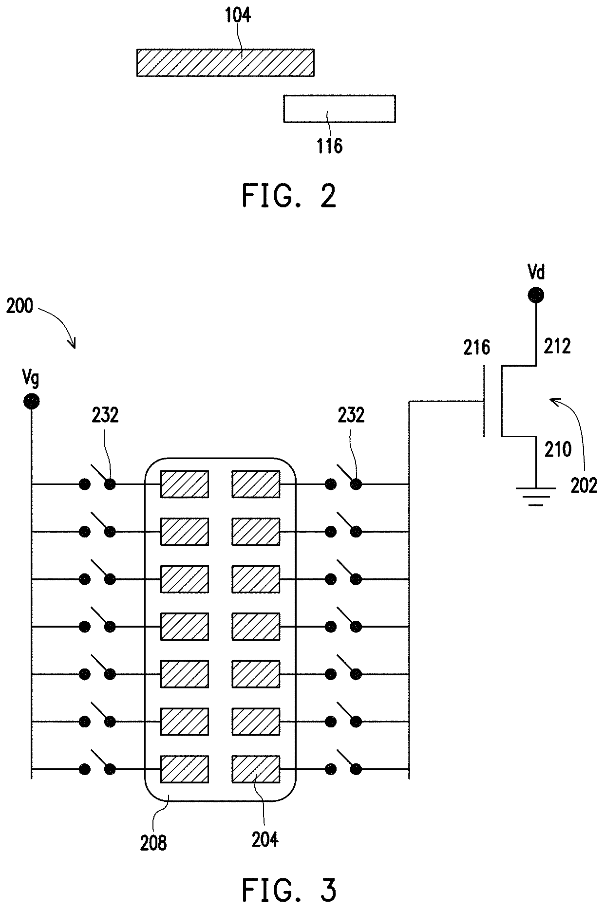
[0068]In experimental example 2, the sensing device 200 shown in FIG. 3 was used for the test, wherein a specific aptamer of a C-reactive protein was bonded on the response electrode of the sensing device.

[0069]A reference protein solution containing 4% bovine serum albumin (BSA) was made via phosphate buffer saline (PBS), and the reference protein solution was added dropwise in the gap between the response electrode and the base, and the measurement conditions are as follows: Vd=2V, Vg=1 V, pulse time=100 μs. A first current I1 was measured at the drain end of the base.

[0070]Next, the bovine serum albumin solution between the response electrode and the base was washed away by an elution buffer. The reference protein solution containing 4% bovine serum albumin was used as a solvent, C-reactive protein was used as a solute, and a C-reactive protein solution having a concentration of 0.5 mg / L was made.

[0071]Next, the C-reactive protein solution was added dropwise on the response elect...

experimental example 3 to experimental example 6

[0074]Measurement was performed with substantially the same method as experimental example 2, and the difference is only in that the concentrations of the C-reactive protein solutions made in experimental example 3 to experimental example 6 were respectively 1.0 mg / L, 3.0 mg / L, 5.0 mg / L, and 10.0 mg / L.

[0075]FIG. 7 shows the relationship between Δ gain value and concentration of experimental example 2 to experimental example 6. It can be known from FIG. 7 that, Δ gain value is increased with increased concentration of C-reactive protein and a significant correlation is observed.


PUM

PropertyMeasurementUnit
electric fieldaaaaaaaaaa
concentrationaaaaaaaaaa
concentrationsaaaaaaaaaa

Abstract

A detecting method for blood is provided. The method includes the following steps. A sensing device including a base and at least one response electrode is provided, wherein the response electrode is spaced apart from a gate end of the base. Blood including blood cells and targets is disposed on the response electrode. The blood is separated into a first part and a second part, wherein the first part is in contact with the response electrode, and the blood cell count in the first part is less than that in the second part. A voltage is applied on the response electrode, such that an electric field is generated between the response electrode and the gate end of the base, and a detection current generated from the base is measured to detect a characterize of the targets.

Description

CROSS-REFERENCE TO RELATED APPLICATION[0001]This application claims the priority benefit of Taiwan application serial no. 106141700, filed on Nov. 29, 2017. The entirety of the above-mentioned patent application is hereby incorporated by reference herein and made a part of this specification.BACKGROUND OF THE INVENTIONField of the Invention[0002]The invention relates to a biological sample detecting method, and more particularly, to a blood detecting method.Description of Related Art[0003]The blood detection is one of the important test items in a health examination. In clinical blood detection, the main treatment process is divided into three major steps, which are respectively blood sample extraction, blood sample pretreatment, and detecting. To reduce interference caused by blood cells, the blood sample is usually pretreated to separate the blood cells and plasma, and then the target in the plasma is tested to obtain an accurate test value.[0004]Current methods for separating blo...

Claims


Application Information

Patent Timeline
Patent Type & Authority Patents(United States)
IPC IPC(8): G01N33/543G01N27/414G01N33/50G01N33/49
CPCG01N27/4145G01N27/414G01N33/49G01N33/5091G01N33/5438
Inventor WANG, YU-LINSARANGADHARAN, INDUWANG, SHIN-LI
Owner NATIONAL TSING HUA UNIVERSITY
Learn More