Wireless communications networks

a technology of wireless communication and mesh communication, applied in the field of wireless mesh communications network, can solve the problems of today's data traffic requirements, techniques are subject to interference, and no longer able to meet data throughput rates

Active Publication Date: 2022-05-10
BLUWIRELESS TECH
View PDF14 Cites 0 Cited by
  • Summary
  • Abstract
  • Description
  • Claims
  • Application Information

AI Technical Summary

Benefits of technology

[0008]In accordance with the principles of the present invention, baseband centre frequencies allocated to communications links in a wireless mesh communications network are offset from one another by frequency offset values, in order to mitigate start-of-packet detection interference. The frequency offset values are typically very small relative to the bandwidth and / or symbol rate of the communication links, and specifically are typically less than a fifth of the channel bandwidth and / or symbol rate. Such a technique is particularly suitable for use in a millimetre wave wireless network, such as that defined by IEEE standard 802.11ad, operating in the 60 GHz waveband.

Problems solved by technology

Early wireless mesh networks employed Wi-Fi technology with omnidirectional antenna but are no longer able to meet the data throughput rates (measured across the mesh from one edge node to another) of today's data traffic requirements.
In addition, such techniques are subject to interference as the unlicensed 5 GHz band becomes more congested.
In a wireless mesh network, various modes of interference can occur, either between network nodes, or between transceivers in a network node device.
A significant interference mode is one that causes start of packet (SoP) detection errors in a receiver.
In the case when an erroneous packet is misinterpreted as the correct data packet, then delay and packet loss occurs due to the time taken to decode and discard the erroneous packet.

Method used


Image

  • Wireless communications networks
  • Wireless communications networks
  • Wireless communications networks

Examples


Embodiment Construction

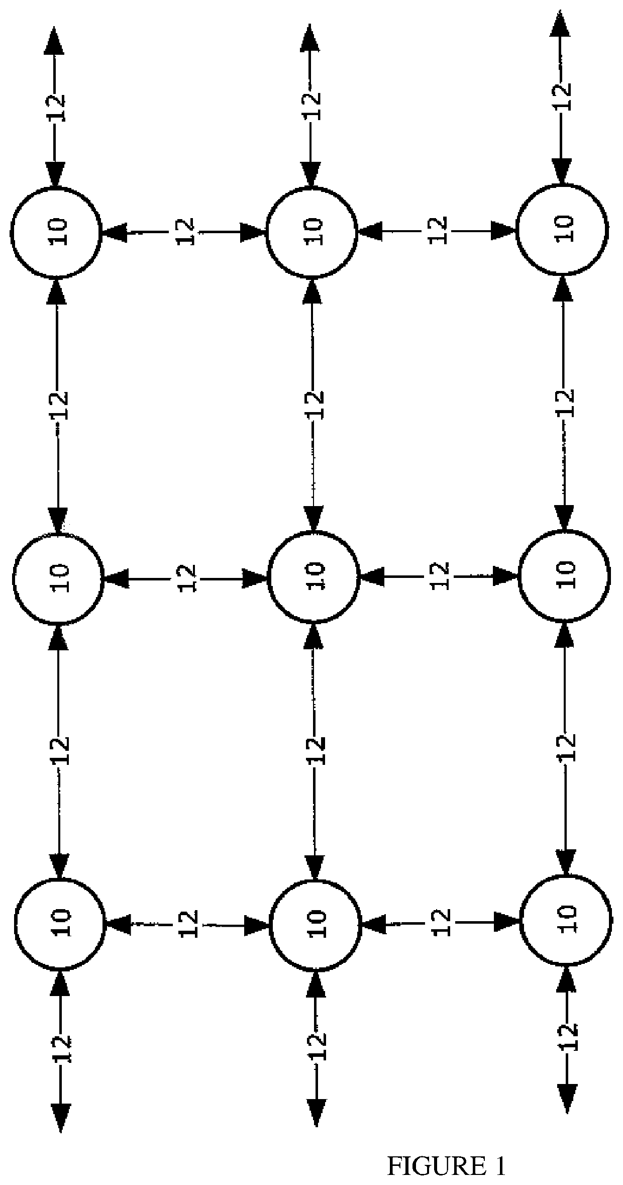
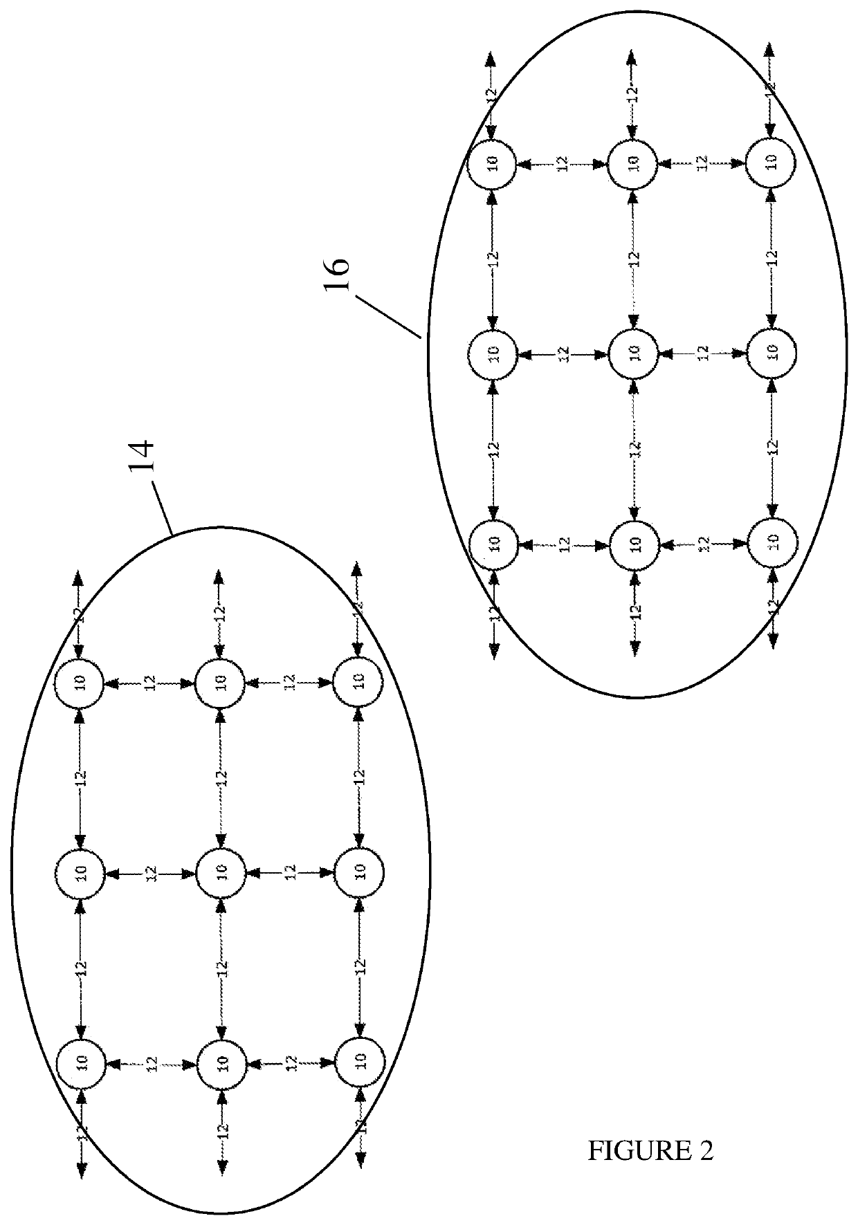
[0044]FIG. 1 illustrates an “ideal” grid-like mesh communications network in which the network node devices 10 are arranged in a regular, predictable grid. As such, organisation of the network node devices 10 is into a usable, optimal or near optimal communications topology. As mentioned above, FIG. 1 illustrates a simplified example wireless mesh communications network which comprises a plurality of network node devices 10 interconnected by bidirectional wireless communications links 12. The network node devices 10 operate to communicate with one another, for the transfer of communications data therebetween. This type of network is known as a “mesh” network and uses multiple connections between network node devices that defines a mesh of communications links 12. FIG. 2 illustrates a pair of adjacent mesh communications networks 14 and 16, each being in line with the mesh network of FIG. 1. FIG. 2 is intended to illustrate that different mesh networks may be adjacent one another.

[00...


PUM


Abstract

A method of mitigating start-of-packet interference in a millimetre waveband wireless mesh communications network which comprises a first plurality of network node devices each having a transceiver unit which includes a beamforming antenna device, and a second plurality of millimetre waveband wireless communications links each of which interconnects a respective pair of the transceiver units of the network node devices, the method comprising: allocating respective baseband centre frequencies to pairs of transceivers of the network node devices, which baseband centre frequencies are for use with respective communications links of the network, each such allocated baseband centre frequency being offset from at least one other allocated baseband centre frequency by a respective predetermined offset amount; and at a first transceiver of a selected pair of transceivers, encoding a data packet using an encoding signal having the baseband centre frequency allocated to the selected pair of transceivers, to generate an encoded signal.

Description

[0001]The present invention relates to wireless communications networks, and in particular to wireless mesh communications networks.BACKGROUND OF THE INVENTION[0002]FIG. 1 of the accompanying drawings illustrates a simplified example wireless mesh communications network which comprises a plurality of network node devices 10 interconnected by bidirectional wireless communications links 12. The network node devices 10 operate to communicate with one another, for the transfer of communications data therebetween. This type of network is known as a “mesh” network and employs the multiple connections between network node devices that defines a mesh of communications links 12.[0003]Wireless mesh networks are strong candidates to provide data communications, for example for Internet access, or for backhaul data traffic from small cell base stations. This is primarily because such wireless mesh networks require no cabling and can be deployed and extended in a flexible manner. Transmission an...

Claims


Application Information

Patent Timeline
Patent Type & Authority Patents(United States)
IPC IPC(8): H04W4/00H04W72/08H04B7/06H04W72/04
CPCH04W72/082H04B7/0617H04W72/0453H04W84/18H04W72/541H04B1/707H04B2001/0491H04W72/56
Inventor MCCONNELL, RAYMOND MARK
Owner BLUWIRELESS TECH
Why Eureka
Try Eureka