
Method for locating a target and multistatic radar system for implementing such a method

Active Publication Date: 2019-05-07
THALES SA
View PDF18 Cites 0 Cited by
  • Summary
  • Abstract
  • Description
  • Claims
  • Application Information

AI Technical Summary

Benefits of technology

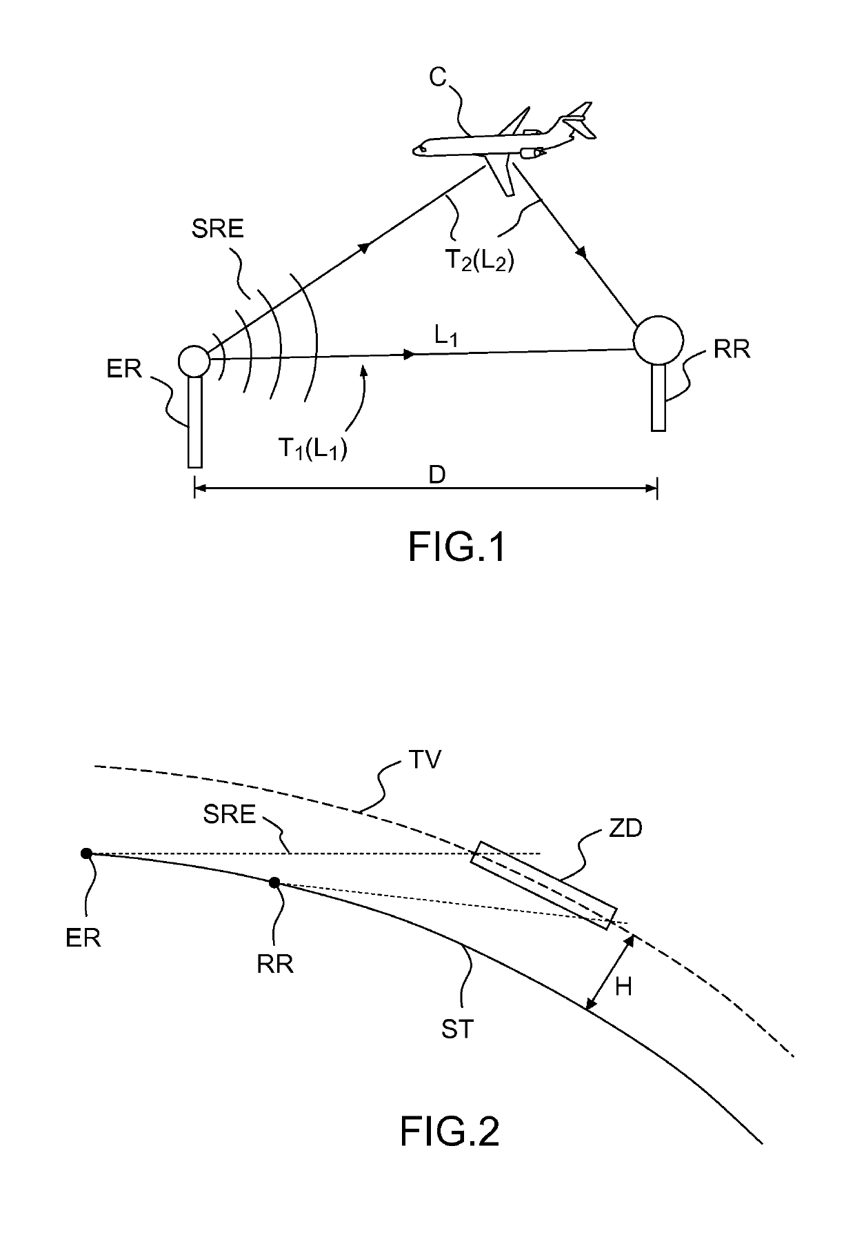
The invention allows for using a data transmission link to transmit reference signals, which makes it possible to arrange receivers at a farther distance from the transmitter than if the line of sight condition had to be met. This is achieved through iterative synchronization of replicas with a common temporal reference, using sets of three bistatic distances or temporal markers contained in the radioelectric signals and reference signals. The technical effect is improved efficiency and flexibility in transmitting reference signals, allowing for greater distances between receivers and transmitters.

Problems solved by technology

Purely passive systems are not appropriate for applications as critical as air traffic monitoring; however, it would be possible—at least in principle—to produce “semi-active” systems, using opportunity transmitters according to a cooperative modality, based on an agreement with the operators of these transmitters.
It is easily understood that, for direct propagation to be possible, the transmitter and the receiver must be “in line of sight” thereby implying that, on account of the curvature of the Earth, their distance may hardly exceed a few tens of kilometers, unless at least one of the two is placed at a high altitude, this not always being possible or desirable.
This limits the choice of the opportunity transmitters that may be used for air traffic monitoring.
Indeed, the use of FM radiophonic transmitters (bandwidth of about 20 kHz) leads to uncertainties of the order of 1 km and is therefore unsuitable for the monitoring of civil air traffic (although it is appropriate for other applications, for example for aircraft detection), while television signals (bandwidth of about 10 MHz) make it possible to achieve uncertainties of the order of 20 m, this being satisfactory for civil air traffic monitoring.
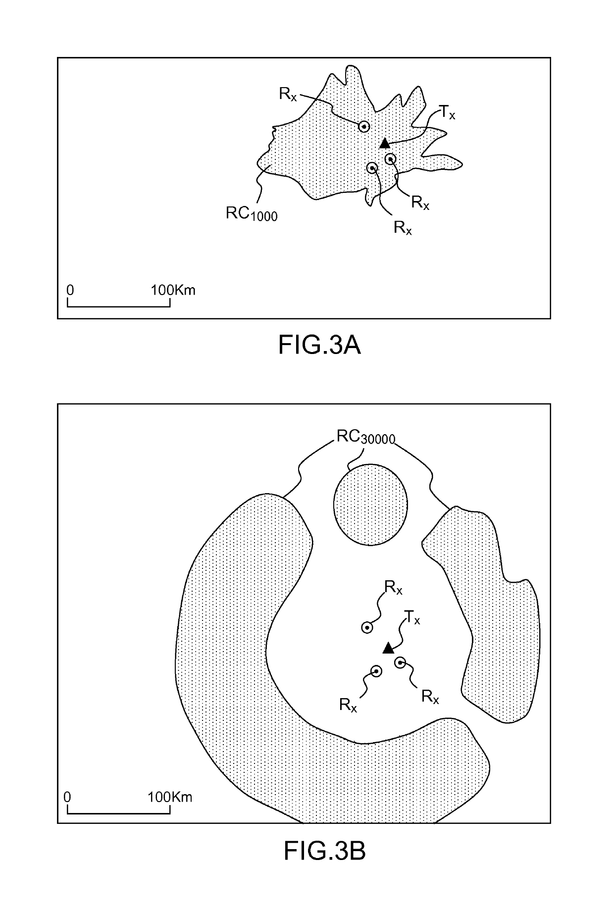
It is readily understood that it is not practical to carry out full coverage of a territory by using ring-shaped detection regions, all the more so as the location of the television transmitters is not optimized for this application.
Moreover, the passive location of a target situated at a distance of several hundred kilometers from the transmitters and receivers would be rendered difficult by the significant attenuation undergone by the signals.
Furthermore, the integration of the signals received can only be done over the duration of the predefined sequences, which are generally fairly brief; this implies that the method can only operate under good signal-to-noise ratio conditions.
Such a technique can only operate under restrictive assumptions, notably a high signal-to-noise ratio.

Method used


Image

  • Method for locating a target and multistatic radar system for implementing such a method
  • Method for locating a target and multistatic radar system for implementing such a method
  • Method for locating a target and multistatic radar system for implementing such a method

Examples


first embodiment

[0059]FIG. 5 illustrates in greater detail the structure and the operation of a detection system according to the invention. The transmitter ER is a digital television transmitter, which receives from a central broadcasting station SCD a digital source signal SS which represents the succession of bytes constituting an MPEG file. This signal drives a digital modulator MOD, parametrized with modulation parameters specific to the transmitter, which generates a signal at intermediate frequency. This signal:

[0060]on the one hand, is converted to radiofrequency so as to be irradiated by a transmit antenna in the form of a radioelectric signal SRE;

[0061]on the other hand is sampled and quantized so as to be transmitted in digital format along the data transmission line LD, in the form of a digital reference signal SLD. At the level of the receiver RR, a replica reconstruction module RSR uses this digital signal to reconstruct or regenerate a signal SREF “imitating” a signal which would hav...

second embodiment

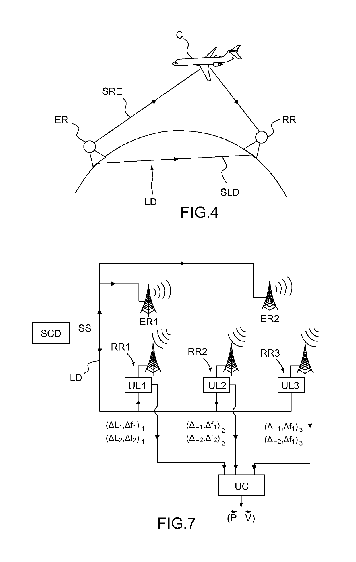
[0065]FIG. 7 schematically illustrates the general structure of a system according to said This system comprises a central broadcasting station SCD transmitting the source signal SS to two transmitters ER1, ER2 and (by way of the data transmission line LD) to three receivers RR1, RR2, RR3. Each receiver comprises an antenna and a local data processing unit UL1-UL3. Each said local processing unit comprises the blocks for modulation, reconstruction of the replicas and cross-correlation whose manner of operation was described above, and generates two pairs of values (ΔLi, Δfi)j, where “i” identifies the transmitter (i=1,2) and “j” the receiver (j=1,2,3). These values are transmitted to the central processing unit UC, which makes use thereof to calculate the position {right arrow over (P)} and the velocity {right arrow over (V)} of the (or of each) target.

[0066]It will be noted that, to locate a target, three values ΔLi suffice. Now, in the system of FIG. 7 there are six of these valu...


PUM


Abstract

A method for locating a target comprises: a) receiving, by means of N≥1 receivers, opportunity radioelectric signals transmitted by M≥1 transmitters and reflected by the target, with N·M≥3, or at least one transmitter being situated out of sight of at least one receiver; b) receiving, by means of a data transmission link, one or more reference signals, representative of the radioelectric signals transmitted by each transmitter situated out of sight of at least one receiver; and c) determining the position of the target on the basis of the radioelectric signals and of the reference signal or of the reference signals. An application of the method to the primary monitoring of air traffic, a multistatic radar system for the implementation of the method, and a system for monitoring air traffic comprising a multistatic radar system are provided.

Description

CROSS-REFERENCE TO RELATED APPLICATIONS[0001]This application is a National Stage of International patent application PCT / EP2014 / 060539, filed on May 22, 2014, which claims priority to foreign French patent application No. FR 1301182, filed on May 24, 2013, the disclosures of which are incorporated by reference in their entirety.FIELD OF THE INVENTION[0002]The invention pertains to a method for detecting and locating a target which may be notably an aircraft, to its application to the primary monitoring of air traffic, to a multistatic radar system for the implementation of such a method and to a system for monitoring air traffic comprising such a multistatic radar system.[0003]The invention applies notably to the primary monitoring of air traffic by means of opportunity signals such as television signals.BACKGROUND[0004]The primary monitoring (without cooperation on the part of the aircraft-targets) of air traffic is conventionally done by means of “monostatic” radars, which transm...

Claims


Application Information

Patent Timeline
IPC IPC(8): G01S7/40G01S13/87G01S7/41G01S13/42G01S13/58G01S13/00
CPCG01S13/003G01S7/4021G01S13/872G01S13/42G01S13/58G01S7/418
Inventor MULLER, DANIEL
Owner THALES SA
Learn More